
User's Manual

CHAPTER 8
ANTENNA SETUPS
Revised: 2 Jul 08 8-9 EST P/N AA107G
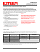
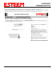
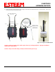
9. Route the CAT-5e Ethernet cable through the molded strain-relief fins in the Face Plate Cover (Figure 8) to secure the cable
and provide strain-relief for the connector. If a second Ethernet cable is installed, remove the second port cover and route
cable.
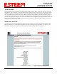
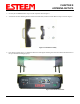
10. Plug the CAT-5e Ethernet cable to the Model 195Eg’s Ethernet port and secure the Face Plate Cover with the attached thumb
screw. Verify that the weatherproof seal on the Face Plate Cover is sealed against the outer rim of the Model 195Eg.
Reference Figure 9.
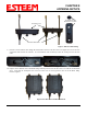
Figure 7: Ethernet Cable Routing
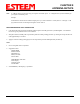
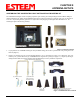
Figure 8: Face Plate Cover Strain Relief
Figure 9: Face Plate Cover Installed on ESTeem
Face Plate Cover
Ethernet Cable Boots
Second Port Cover
Remove for 2
nd
Cable