
User's Manual

CHAPTER 8
ANTENNA SETUPS
Revised: 2 Jul 08 8-8 EST P/N AA107G
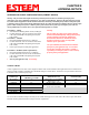
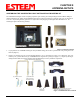
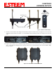
6. Attach the two Pole Mounting Brackets to the ESTeem Model 195Eg with the 10-24 x 1” Phillips Pan Head screws through
the top of the heat shield. Reference Figure 5 (Heat Shield removed for detail).
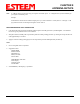
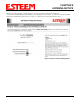
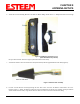
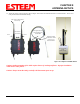
7. Assemble the outdoor rated CAT-5e Ethernet cable (Not Provided) with the supplied Ethernet Cable Boot (Figure 6).
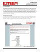
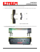
8. Feed the CAT-5e Ethernet connector(s) through the Face Plate Cover and secure the Ethernet Cable Boot to the cover.
Reference Figure 7. NOTE: The Ethernet cable boot must be installed before the RJ-45 end is installed. If using the ESTeem
AA09.1 outdoor Ethernet cable, verify that the Ethernet cable boot end is routed toward the ESTeem 195Eg.
Figure 5: Pole Mount Connection to Case
(Heat Shield Removed for Detail)
Ethernet Cable Boot
Figure 6: Ethernet Cable Assembly