
User's Manual

CHAPTER 8
ANTENNA SETUPS
Revised: 2 Jul 08 8-1 EST P/N AA107G
ANTENNA AND CABLE CONFIGURATIONS (POLE MOUNT)
EST offers different types of antennas for both indoor and outdoor configurations. To reduce potential radio interference to other
users, the antenna type and its gain should be so chosen that the equivalent isotropically radiated power (e.i.r.p.) is not more than
that permitted for successful communication.
Warning: Only the tested cable lengths and antennas provided by EST meet the FCC maximum peak output power
requirements. Any other combination of antennas or coax cables is not authorized. This device has been designed to operate in
a pole mount configuration with the antennas listed below, and having a maximum gain of 6 dB in a multi-point system or
19dB in a point to point network. Antennas not included in this list or having a gain greater 6 dB in a multi-point system or
19dB in a point to point network are strictly prohibited for use with this device. The required antenna impedance is 50 ohms.
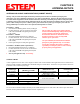
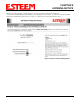
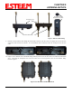
Part Number: AA01S
•
••
• Omni-directional, rubber duck, direct mount, unity gain
antenna.
•
••
• Indoors and short range outdoor applications.
•
••
• There must be a minimum separation distance of 20
cm. from the antenna to the user. See Warnings.
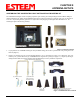
Part Number: AA20DMEg
•
••
• Omni-directional direct mount antenna, 5 dBi gain.
•
••
• Indoor and outdoor applications.
•
••
• There must be a minimum separation distance of 20
cm. from the antenna to the user. See Warnings.
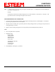
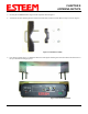
Part Number: AA20Eg
•
••
• Omni-directional external pole mount antenna, 6 dBi
gain with 3-ft. integral feedline and connector.
•
••
• Outdoor applications.
•
••
• Antenna port B is not used in this configuration.
•
••
• There must be a minimum separation distance of 20
cm. from the antenna to the user. See Warnings.
Part Number: AA203Eg
•
••
• Directional pole mount antenna, 6 dBi gain with 3-ft.
integral feedline and connector.
•
••
• Point to point and point to multi-point outdoor
applications.
•
••
• Antenna port B is not used in this configuration.
•
••
• There must be a minimum separation distance of 20
cm. from the antenna to the user. See Warnings.
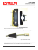
Part Number: AA204Eg
•
••
• Directional pole mount antenna, 19 dBi gain with 3-ft.
integral feedline and connector.
•
••
• Point to point applications only.
•
••
• Maximum Output Power of 250mWatts (Power Level
= Low Power)
•
••
• Antenna port B is not used in this configuration.
•
••
• There must be a minimum separation distance of 50
cm. from the antenna to the user. See Warnings.
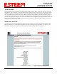
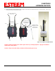
Transmit/Receive
Antenna Port
Receive Only
Antenna Port
Notes:
Antenna Port A is a transmit and receive port for use in all
applications.
Antenna Port B is a receive only port and is used for dual
diversity antennas applications only. This port is not used
for point to point applications.
Warnings:
Only pre-made coax cables from the factory used in
conjunction with either the AA20Eg omni-directional
and AA203Eg or AA204Eg directional antennas meet all
FCC Section 15.247(b) EIRP maximum power
requirements.
Use of the AA204Eg, directional antenna is limited to
fixed point to point applications only. In accordance
FCC Section 15.247(b)iii, this antenna must be
professionally installed. The installer must ensure the
system is used exclusively for fixed, point-to-point
applications and the ESTeem Model 195Eg is set for 0.25
Watts output power (Power Level = Min).