
User's Manual

CHAPTER 1
INTRODUCTION
Revised: 23 Jan 08 1-4 EST P/N AA107G
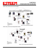
Point Router mode, the wireless and wired Ethernet networks will need to be on separate subnets. To communicate from
wireless network to devices on the wired Station Router network, a separate router (connected to the Ethernet side of the
Access Point) is required. This mode would be used where multiple Ethernet devices will be connected to a single Model
195Eg in a mobile client application and the connected Ethernet devices will need to be accessible from the Access Point’s
LAN network.
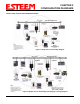
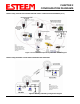
8. Station Masquerade Mode. The Station Masquerade Mode is another mode where multiple devices will be connected to a
single ESTeem in a mobile or Client application, but unlike the Station Router mode, the Station Masquerate will consolidate
all connected Ethernet devices to a single IP address on the network. The devices connected to the Station Masquerade 195Eg
will be able to access information from both the wireless and wired LAN, but will be inaccessible the other way similar in
application to a firewall. This mode would be used where multiple Ethernet devices will be connected to a single Model
195Eg in a mobile application and the IP addresses for each device will be hidden from the LAN connected to the Access
Point. See Figure 3.
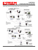
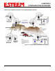
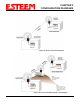
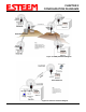
9. Serial Applications (Optional). The ESTeem 195Eg can optionally be installed with an RS-232 data port for serial data
applications run over the broadband link (Figure 5). The serial over broadband network can be used in a point-to-point or
point-to-multi-point application for networking serial (RS-232c) devices, providing serial connections to legacy hardware in a
new Ethernet network or providing for high-bandwidth devices (such as Video or Voice over IP) in an existing serial network.
Installing the serial port option also provides a second 10/100 Base-T Ethernet port that can be used to connect a second
Ethernet device without requiring a HUB/Switch or can be configured as an external Router port.
To begin setup of your wireless Ethernet network you must first configure the Model 195Eg for the mode desired. Chapter 2 will
show several examples of the different modes of operation to help select the correct mode for your application.
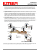
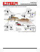
Remote Site & Repeater
Repeater
Remote Site
Access Point
Bridge with
Repeater Mode
Remote Site
Access Point
Bridge with
Repeater
Mode
Access Point
Bridge with
Repeater
Mode
Access Point
Bridge with
Repeater Mode
Access Point
Bridge with
Repeater
Mode
L
i
n
e
-
o
f
-
S
i
g
h
t
P
a
t
h
NOTE:
Repeater may be stand-
alone or attached to a
network or device.
L
i
n
e
-
o
f
-
S
i
g
h
t
P
a
t
h
L
i
n
e
-
o
f
-
S
i
g
h
t
P
a
t
h
L
i
n
e
-
o
f
-
S
i
g
h
t
P
a
t
h
L
in
e
-
o
f
-
S
i
g
h
t
P
a
t
h
Access Point
Bridge with
Repeater
Mode
Note:
Antenna’s shown are for
illustration purposes. There
are many antenna options
available depending on your
application.
Master PLC
RS-232 Data
Remote PLC
RS-232 Data
RS-232 Data
RS-232 Data
RS-232 Data
Figure 5 – Multi-point Serial Diagram