ESTeem MODEL 195Eg USER’S MANUAL Manual Revision 2.5 June 2008 Electronic Systems Technology, Inc.
ESTeem MODEL 195Eg USER’S MANUAL Manual Revision 2.5 Firmware Version 302.8.102 and above June 2008 Prepared by: Name: Title: Eric P. Marske Product Manager Date: Approved by: Name: Title: Tom L.
COPYRIGHT INFORMATION This manual and the firmware described in it are copyrighted by EST, with all rights reserved. Under the copyright laws, this manual or the firmware internal to the ESTeem unit may not be copied, in whole or part, without the written consent of EST. Under the law, copying includes translating into another language.
TABLE OF CONTENTS CHAPTER 1 – INTRODUCTION Before You Begin 1-1 Model 195Eg Overview 1-1 ----------------------------------------------------------------------------------------------------------------------------------------------------------------------------------------------------------------------------- 1-1 1-2 1-3 1-3 1-3 1-4 Model 195Eg Access Point Configurations Figure 1: Single Access Point Bridge Diagram Figure 2: Multiple Access Point Bridge Diagram Figure 3: Access Point Router Diagram F
TABLE OF CONTENTS ESTeem Discovery Utility Installation Operation Configuring the IP Address ------------------------------------------------------------------------------------------------------------------------------------- 3-5 3-5 3-6 3-6 Using The RS-232 Interface Installing ESTeem Utility Program Programming Using the RS-232 Port ----------------------------------------------------------------------------------------- 3-7 3-7 3-7 CHAPTER 4 – WEB CONFIGURATION 4-1 Logging Into Web Configuration
TABLE OF CONTENTS 6-1 Serial Configuration CHAPTER 7 – REPEATING FEATURES Overview ESTeem Mesh Network Configuration --------------------------------------------- 7-1 7-1 7-1 Spanning Tree Protocol (STP) Overview Phases Priority and Path Cost Root Bridge --------------------------------------------------------------------------------------------------------------------------------------------------------------------------------- 7-2 7-2 7-3 7-4 7-4 7-5 Redundant Backup CHAPTER 8 – ANTENNA SETUPS A
TABLE OF CONTENTS APPENDIX D – RADIO CONFIGURATION Frequency of Operation Setting Data Rates Setting RF Power Level Average RF Output Power --------------------------------------------------------------------------------------------------------------------------------------------------------------------------------- D-1 D-1 D-3 D-4 -------------------------------------------------------------------------------------------------------------------------------------------------------------------------------
CHAPTER 1 INTRODUCTION BEFORE YOU BEGIN Thank you and congratulations on your purchase of the ESTeem Model 195Eg Wireless Ethernet Radio Modem! This manual was written to help both the first time and advanced user of the 195Eg configure the radio modem for your application. If this your first time configuring the 195Eg and you would like to get going as soon as possible, we recommend using the 195Eg Quick Start Guide provided with the modem.
CHAPTER 1 INTRODUCTION MODEL 195Eg CONFIGURATION MODES The Model 195Eg can be configured for multiple modes of operation without any changes to the hardware: Access Point Modes 1. Access Point Bridge Mode. When the Model 195Eg is configured as an Access Point it will provide a wireless bridge from a hardwired Local Area Network (LAN) to laptops, office computers, Personal Digital Assistants (PDA’s), video cameras, PLC’s, etc. that have integral or external 802.11g or 802.
CHAPTER 1 INTRODUCTION be rejected similar to the operation of a “firewall”. The 195Eg will hide all the IP addresses connected on the wireless link. You should use this mode of operation if Model 195Eg is connected directly to the Internet with a static IP address (DSL, T1, etc.) and you want the wireless clients to access the information through the Model 195Eg (Figure 3).
CHAPTER 1 INTRODUCTION Point Router mode, the wireless and wired Ethernet networks will need to be on separate subnets. To communicate from wireless network to devices on the wired Station Router network, a separate router (connected to the Ethernet side of the Access Point) is required.
CHAPTER 2 CONFIGURATION DIAGRAMS MODEL 195Eg ACCESS POINT BRIDGE DIAGRAMS Figure 1: Single Access Point Bridge Diagram Figure 2: Multiple Access Point Bridge (Overlapping Coverage) Diagram Revised: 23 Jan 08 2-1 EST P/N AA107G
CHAPTER 2 CONFIGURATION DIAGRAMS MODEL 195Eg ACCESS POINT ROUTER DIAGRAM Figure 3: Access Point Router Diagram MODEL 195Eg ACCESS POINT MASQUERADE DIAGRAM Figure 4: Access Point Masquerade Diagram Revised: 23 Jan 08 2-2 EST P/N AA107G
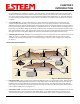
CHAPTER 2 CONFIGURATION DIAGRAMS MODEL 195Eg ACCESS POINT REPEATER AND CLIENT CONFIGURATION DIAGRAMS Figure 5: Access Point Bridge Repeater with Clients Diagram Figure 6: Access Point Router Repeater with Clients Diagram Revised: 23 Jan 08 2-3 EST P/N AA107G
CHAPTER 2 CONFIGURATION DIAGRAMS MODEL 195Eg ACCESS POINT REPEATER AND CLIENT CONFIGURATION DIAGRAMS (Cont.
CHAPTER 2 CONFIGURATION DIAGRAMS MODEL 195Eg BUILDING TO BUILDING CONFIGURATION DIAGRAMS (Cont.
CHAPTER 2 CONFIGURATION DIAGRAMS MODEL 195Eg COMPLETE BRIDGE SYSTEM CONFIGURATION DIAGRAMS Figure 11: Complete Bridge Network Solutions Diagram Revised: 23 Jan 08 2-6 EST P/N AA107G
CHAPTER 2 CONFIGURATION DIAGRAMS MODEL 195Eg COMPLETE ROUTER SYSTEM CONFIGURATION DIAGRAMS Figure 12: Complete Router Network Solutions Diagram Revised: 23 Jan 08 2-7 EST P/N AA107G
CHAPTER 2 CONFIGURATION DIAGRAMS Figure 13: Point to Point Serial Diagram Figure 14: Point to Point With Repeater Serial Diagram Revised: 23 Jan 08 2-8 EST P/N AA107G
CHAPTER 2 CONFIGURATION DIAGRAMS Figure 15: Multi-point Serial Diagram Figure 16: Ethernet and Serial Diagram Revised: 23 Jan 08 2-9 EST P/N AA107G