
User's Manual
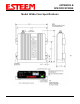
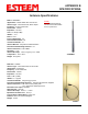
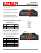
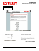
Table Of Contents
- 195Ea Chapter 0 - Front Cover 195Ea
- 195Ea Chapter 0 - Table of Contents
- 195Ea Chapter 1 - Introduction
- 195Ea Chapter 2 - Starting Out
- 195Ea Chapter 3 - Example Applications
- 195Ea Chapter 4 - Utilities and Features
- 195Ea Chapter 5 - Web Configuration Manager
- 195Ea Chapter 6 - Serial Configuration and Applications
- 195Ea Chapter 7 - Repeating and Mesh Networking
- 195Ea Chapter 8 - Antenna Setup
- 195Ea Apx A - FCC Information
- 195Ea Apx B - Specifications
- 195Ea Apx C - Interface Ports
- 195Ea Apx D - Radio Configuration
- 195Ea Apx E - Security
- 195Ea Apx F - Troubleshooting

APPENDIX B
SPECIFICATIONS
Antenna Specifications
Revised: 17 Jan 12 APX B-4 EST P/N AA107A
Model No: AA205Ea
Applications: Fixed base mounting
Antenna Type: Directional, Linear Polarized Panel, DC grounded,
Integral Bandpass Filter
Frequency: 5.725-5.875 GHz
Polarization: Vertical or Horizontal
Impedance: 50 ohms
Gain: 22 dBi (20 dBd) nominal
VSWR: <1.5:1 nominal
Front to Back Ratio: ≥ 25 dB
Horizontal Beamwidth: 9 degrees @ ½ power
Vertical Beamwidth: 9 degrees @ ½ power
Antenna Material: White UV Resistant Polypropylene
Recommended Mounting Hardware: Adjustable Mounting Bracket
provided for wall mounting or masts between 1 in and 2.75 in. O.D.
Antenna Connector: TNC male reverse polarity with 18 in. pig-tail
and weatherproof boot.
Maximum Power Input: 20 Watts
Antenna Envelope: 14.5 in. length by 14.5 in. height by 1.75 in.
depth
Operating Temperature: -40 to +85 F.
Weight: 3.5 lbs.
Model AA205Ea
Caution
To comply with the FCC
exposure compliance
requirements, a separation
distance of at least 50 cm
must be maintained
between the antenna and
all persons.