
User's Manual

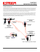
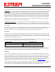
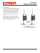
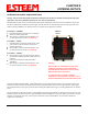
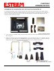
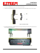
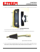
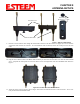
Table Of Contents
- 195Ea Chapter 0 - Front Cover 195Ea
- 195Ea Chapter 0 - Table of Contents
- 195Ea Chapter 1 - Introduction
- 195Ea Chapter 2 - Starting Out
- 195Ea Chapter 3 - Example Applications
- 195Ea Chapter 4 - Utilities and Features
- 195Ea Chapter 5 - Web Configuration Manager
- 195Ea Chapter 6 - Serial Configuration and Applications
- 195Ea Chapter 7 - Repeating and Mesh Networking
- 195Ea Chapter 8 - Antenna Setup
- 195Ea Apx A - FCC Information
- 195Ea Apx B - Specifications
- 195Ea Apx C - Interface Ports
- 195Ea Apx D - Radio Configuration
- 195Ea Apx E - Security
- 195Ea Apx F - Troubleshooting

CHAPTER 8
ANTENNA SETUPS
Revised: 27 Jan 12 8-5 EST P/N AA107A
9. Route the CAT-5e Ethernet cable through the molded strain-relief fins in the Face Plate Cover (Figure 8) to secure the cable
and provide strain-relief for the connector. If a second Ethernet cable is installed, remove the second port cover and route
cable.
10. Plug the CAT-5e Ethernet cable to the Model 195E’s Ethernet port and secure the Face Plate Cover with the attached thumb
screw. Verify that the weatherproof seal on the Face Plate Cover is sealed against the outer rim of the Model 195E. Reference
Figure 9.
11. Attach the antenna connector boots as show in Figure 10 for either dual attached antennas or external antennas. You are now
ready to mount the ESTeem Model 195E
Figure 8: Face Plate Cover Strain Relief
Figure 9: Face Plate Cover Installed on ESTeem
Figure 7: Ethernet Cable Routing
Face Plate Cover
Ethernet Cable Boots
Second Port Cover
Remove for 2
nd
Cable