
User's Manual

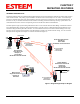
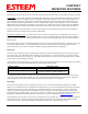
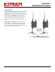
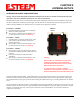
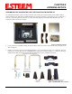
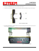
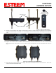
Table Of Contents
- 195Ea Chapter 0 - Front Cover 195Ea
- 195Ea Chapter 0 - Table of Contents
- 195Ea Chapter 1 - Introduction
- 195Ea Chapter 2 - Starting Out
- 195Ea Chapter 3 - Example Applications
- 195Ea Chapter 4 - Utilities and Features
- 195Ea Chapter 5 - Web Configuration Manager
- 195Ea Chapter 6 - Serial Configuration and Applications
- 195Ea Chapter 7 - Repeating and Mesh Networking
- 195Ea Chapter 8 - Antenna Setup
- 195Ea Apx A - FCC Information
- 195Ea Apx B - Specifications
- 195Ea Apx C - Interface Ports
- 195Ea Apx D - Radio Configuration
- 195Ea Apx E - Security
- 195Ea Apx F - Troubleshooting

CHAPTER 8
ANTENNA SETUPS
Revised: 27 Jan 12 8-4 EST P/N AA107A
6. Attach the two Pole Mounting Brackets to the ESTeem Model 195E with the 10-24 x 1” Phillips Pan Head screws through the
top of the heat shield. Reference Figure 5 (Heat Shield removed for detail).
7. Assemble the outdoor rated CAT-5e Ethernet cable (Not Provided) with the supplied Ethernet Cable Boot (Figure 6).
8. Feed the CAT-5e Ethernet connector(s) through the Face Plate Cover and secure the Ethernet Cable Boot to the cover.
Reference Figure 7. NOTE: The Ethernet cable boot must be installed before the RJ-45 end is installed. If using the ESTeem
AA09.1 outdoor Ethernet cable, verify that the Ethernet cable boot end is routed toward the ESTeem 195E.
Figure 5: Pole Mount Connection to Case
(Heat Shield Removed for Detail)
Ethernet Cable Boot
Figure 6: Ethernet Cable Assembly