
User's Manual
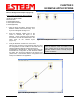
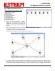
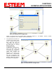
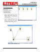
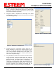
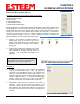
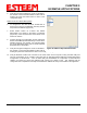
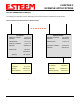
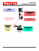
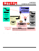
Table Of Contents
- 195Ea Chapter 0 - Front Cover 195Ea
- 195Ea Chapter 0 - Table of Contents
- 195Ea Chapter 1 - Introduction
- 195Ea Chapter 2 - Starting Out
- 195Ea Chapter 3 - Example Applications
- 195Ea Chapter 4 - Utilities and Features
- 195Ea Chapter 5 - Web Configuration Manager
- 195Ea Chapter 6 - Serial Configuration and Applications
- 195Ea Chapter 7 - Repeating and Mesh Networking
- 195Ea Chapter 8 - Antenna Setup
- 195Ea Apx A - FCC Information
- 195Ea Apx B - Specifications
- 195Ea Apx C - Interface Ports
- 195Ea Apx D - Radio Configuration
- 195Ea Apx E - Security
- 195Ea Apx F - Troubleshooting

CHAPTER 3
EXAMPLE APPLICATIONS
Revised: 6 Sep 11 3-11 EST P/N AA107A
Ethernet Router Mode Example (Figure 4)
Point to Multipoint Router Mode
(4) ESTeem Model 195Ea
Serial Numbers:
E-14000 (Router at Network)
E-14001 (Remote Site 1)
E-14002 (Remote Site 2)
E-14003 (Remote Site 3)
1. Using the above procedure for adding
ESTeem Model 195Eas, add the four
ESTeem 195Eas for this example and
rename by location. Your layout should
appear like Figure 18.
2. Move the ESTeem 195Ea icons on the
screen to simulate the layout of the
diagram. Draw connection lines between
the wireless links modems in the same
order as the network layout (Figure 19).
Figure 18: Router Mode Example Modems
Figure 19: Router Example Layout