
User's Manual
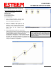
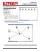
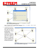
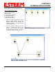
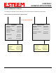
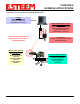
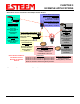
Table Of Contents
- 195Ea Chapter 0 - Front Cover 195Ea
- 195Ea Chapter 0 - Table of Contents
- 195Ea Chapter 1 - Introduction
- 195Ea Chapter 2 - Starting Out
- 195Ea Chapter 3 - Example Applications
- 195Ea Chapter 4 - Utilities and Features
- 195Ea Chapter 5 - Web Configuration Manager
- 195Ea Chapter 6 - Serial Configuration and Applications
- 195Ea Chapter 7 - Repeating and Mesh Networking
- 195Ea Chapter 8 - Antenna Setup
- 195Ea Apx A - FCC Information
- 195Ea Apx B - Specifications
- 195Ea Apx C - Interface Ports
- 195Ea Apx D - Radio Configuration
- 195Ea Apx E - Security
- 195Ea Apx F - Troubleshooting

CHAPTER 3
EXAMPLE APPLICATIONS
Revised: 6 Sep 11 3-10 EST P/N AA107A
indicating a backup link in the repeater Mesh configuration (Figure 17). For detailed instruction on Mesh
network configuration, refer to Chapter 7 of this User’s Manual.
4. Verify all ESTeem modems are
connected to the same switch
as the computer running the
ENC Utility and send the
configuration to all modems at
the same time by selecting
ESTeem>ESTeem
Configuration>Send
Configuration to All ESTeems.
Once the ENC Utility has
downloaded the configuration
for both ESTeem 195Ea’s, the
status box around the
ESTeem‘s will change from
yellow to blue. This indicates
that the configuration was
completed successfully and the
ESTeem 195Ea’s are ready to
be installed in the application.
Figure 17: Mesh Network Configuration
Figure 16: Backup Link Configuration