
User's Manual
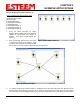
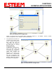
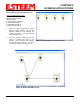
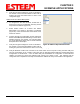
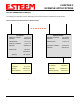
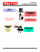
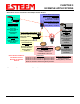
Table Of Contents
- 195Ea Chapter 0 - Front Cover 195Ea
- 195Ea Chapter 0 - Table of Contents
- 195Ea Chapter 1 - Introduction
- 195Ea Chapter 2 - Starting Out
- 195Ea Chapter 3 - Example Applications
- 195Ea Chapter 4 - Utilities and Features
- 195Ea Chapter 5 - Web Configuration Manager
- 195Ea Chapter 6 - Serial Configuration and Applications
- 195Ea Chapter 7 - Repeating and Mesh Networking
- 195Ea Chapter 8 - Antenna Setup
- 195Ea Apx A - FCC Information
- 195Ea Apx B - Specifications
- 195Ea Apx C - Interface Ports
- 195Ea Apx D - Radio Configuration
- 195Ea Apx E - Security
- 195Ea Apx F - Troubleshooting

CHAPTER 3
EXAMPLE APPLICATIONS
Revised: 6 Sep 11 3-9 EST P/N AA107A
Ethernet Bridge Mode Example 3 (Figure 3)
Point to Multipoint with Mesh Repeater Links
(6) ESTeem Model 195Ea
Serial Numbers:
E-14000 (Main Office)
E-14001 (Remote Office)
E-14002 (Repeater)
E-14003 (Remote Site 1)
E-14004 (Remote Site 2)
E-14005 (Remote Site 3)
1. Using the above procedure for adding
ESTeem Model 195Eas, add the six ESTeem
195Eas for this example and rename by
location. Your layout should appear like
Figure 14.
2. Move the ESTeem 195Ea icons on the screen
to simulate the layout of the diagram. Draw
connection lines between the primary wireless
links modems in the same order as the network layout (Figure 15).
3. To create the backup link between Remote 1 and Remote 2 and the other backup link from Remote 2 to the
Remote Office, draw a wireless connection as you would on the primary link. Double-click on the line created.
The Link Editor box will be displayed (Figure 16). Any Path Length greater than 1 will display as a dashed line
Figure 14: Example 3 Modems
Figure 15: Example 2 Layout