
User's Manual
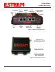
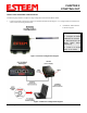
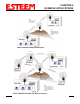
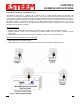
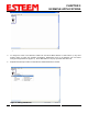
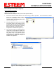
Table Of Contents
- 195Ea Chapter 0 - Front Cover 195Ea
- 195Ea Chapter 0 - Table of Contents
- 195Ea Chapter 1 - Introduction
- 195Ea Chapter 2 - Starting Out
- 195Ea Chapter 3 - Example Applications
- 195Ea Chapter 4 - Utilities and Features
- 195Ea Chapter 5 - Web Configuration Manager
- 195Ea Chapter 6 - Serial Configuration and Applications
- 195Ea Chapter 7 - Repeating and Mesh Networking
- 195Ea Chapter 8 - Antenna Setup
- 195Ea Apx A - FCC Information
- 195Ea Apx B - Specifications
- 195Ea Apx C - Interface Ports
- 195Ea Apx D - Radio Configuration
- 195Ea Apx E - Security
- 195Ea Apx F - Troubleshooting

CHAPTER 2
STARTING OUT
Revised: 23 Aug 11 2-3 EST P/N AA107A
MODEL 195Ea HARDWARE CONFIGURATION
The following steps should be completed to begin configuration of the ESTeem Model 195Ea:
1. Connect the antenna to the antenna connector on the ESTeem Model 195Ea (Figure 3). For a single antenna use Antenna Port
A and connect both if using dual antennas.
2. Assemble the 195Ea hardware
as shown in Figure 4.
Figure 3: Antenna Configuration Diagram
Technical Tips:
1. Configure the Model
195Ea prior to mounting.
2. Attach antenna to the
Model 195Ea before
powering up.
3. There is no On/Off
switch on the 195Ea.
Figure 4: Hardware Configuration Diagram
AA175.2
Power Supply