
User's Manual
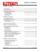
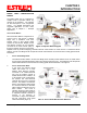
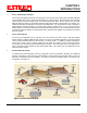
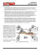
Table Of Contents
- 195Ea Chapter 0 - Front Cover 195Ea
- 195Ea Chapter 0 - Table of Contents
- 195Ea Chapter 1 - Introduction
- 195Ea Chapter 2 - Starting Out
- 195Ea Chapter 3 - Example Applications
- 195Ea Chapter 4 - Utilities and Features
- 195Ea Chapter 5 - Web Configuration Manager
- 195Ea Chapter 6 - Serial Configuration and Applications
- 195Ea Chapter 7 - Repeating and Mesh Networking
- 195Ea Chapter 8 - Antenna Setup
- 195Ea Apx A - FCC Information
- 195Ea Apx B - Specifications
- 195Ea Apx C - Interface Ports
- 195Ea Apx D - Radio Configuration
- 195Ea Apx E - Security
- 195Ea Apx F - Troubleshooting

CHAPTER 1
INTRODUCTION
Revised: 22 Aug 11 1-4 EST P/N AA107A
Station (Client) Modes
1. EtherStation Mode. When the 195Ea is configured in the EtherStation Mode and attached to a single Ethernet
Device, the Model 195Ea will provide wireless mobile access to that device through a canopy of Access Points.
The 195Ea will seamless roam under the radio canopy of Access Point and can provide greatly increased range for
mobile Ethernet devices such as vehicles, forklifts, cranes, etc (Figures 1-3).
2. Station Router Mode. The Station Router mode will also function as a client, similar to EtherStation, but will allow
multiple Ethernet devices to be connected to a single 195Ea (Figure 3). The 195Ea will function as a router
between the wireless client mode and the wired Ethernet devices connected to the Ethernet port. Similar in
configuration to the Access Point Router mode, the wireless and wired Ethernet networks will need to be on
separate subnets. To communicate from wireless network to devices on the wired Station Router network, a
separate router (connected to the Ethernet side of the Access Point) is required. This mode would be used where
multiple Ethernet devices will be connected to a single Model 195Ea in a mobile client application and the
connected Ethernet devices will need to be accessible from the Access Point’s LAN network.
3. Station Masquerade Mode. The Station Masquerade Mode is another mode where multiple devices will be
connected to a single ESTeem in a mobile or Client application, but unlike the Station Router mode, the Station
Masquerade will consolidate all connected Ethernet devices to a single IP address on the network. The devices
connected to the Station Masquerade 195Ea will be able to access information from both the wireless and wired
LAN, but will be inaccessible the other way similar in application to a firewall. This mode would be used where
multiple Ethernet devices will be connected to a single Model 195Ea in a mobile application and the IP addresses
for each device will be hidden from the LAN connected to the Access Point. See Figure 3.
Serial Applications. The ESTeem 195Ea
is installed with an RS-232 data port for
serial data applications run over the
broadband link (Figure 5). The serial over
broadband network can be used in a point-
to-point or point-to-multi-point application
for networking serial (RS-232c) devices,
providing serial connections to legacy
hardware in a new Ethernet network or
providing for high-bandwidth devices (such
as Video or Voice over IP) in an existing
serial network. Installing the serial port
option also provides a second 10/100
Base-T Ethernet port that can be used to
connect a second Ethernet device without
requiring a HUB/Switch or can be
configured as an external Router port.
To begin setup of your wireless Ethernet
network, continue to Chapter 2 - Staring
Out of this User’s Manual.
Figure 6: Multi-point Serial Diagram