
User's Manual Part 2


CHAPTER 7
REPEATING FEATURES
Revised: 1 Oct 13 7-4 EST P/N AA107-195CM
determine routing and which paths will be blocked. On a wired Ethernet network, the location of the Root Bridge is not really
important, but in a wireless network selection of the Root Bridge is critical to the wireless network routing. Let’s use one of the
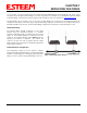
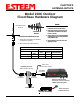
Example network diagrams from Chapter 3 to continue the discussion (Figure 4).
STP Phases
The following sections describe the process of the STP in the ESTeem Model 195C/M as how it would happen in the above
example.
Learning Phase - Once properly configured, each Model 195C/M will begin to search out the other Model 195C/M units in radio
range that are programmed in the AP Repeater Peer table. All Model 195C/M’s will calculate their routes to every Model 195C/M
in the network based upon the lowest “path length” to the Root Bridge. Path length is the total number of wireless links (repeater
peer links) to transmit a packet through the wireless network to the Root Bridge. Note: The Root Bridge in a network should be
the Model 195C/M where the majority of the data flow is processed. In every wireless network of two or more radios, the Root
Bridge should be user defined. If not defined, the ESTeem 195C/M with the lowest MAC address will be designated as the Root
Bridge.
In Figure 4, the Plant network (Example 1) is the most logical location for the Root Bridge based upon the amount of data flow.
Setting this site as the root bridge is discussed below in Root Bridge.
Blocking and Forwarding Phase – To ensure you do not have a network loop situation due to redundant paths in your wireless
network, the Model 195C/M will recognize and disable (block) one or more redundant links and provide back up links should the
primary link fail. This establishes a wireless mesh network with a series of forwarding links, based upon the shortest path length to
the Root Bridge.
For example, looking at Figure 4, the Remote Building has two routes to the Root Bridge (Plant Network – Example #1); directly
to the site and through the repeater. The direct link between the two sites is the shortest route (lowest Path Length) and will be
selected as the primary route unless overridden by manually changing the Path Length in the configuration.
Path Length
If more than one communication path to the Root Bridge is found, the 195C/M must determine which route to take based upon the
lowest Path Length. The default path length to all links in the 195C/M network is 1. If the Path Lengths are equal then the lowest
MAC address will determine the priority route. In the ESTeem Mesh Network we want to directly control all data flow so do not
want the routes to be automatically determined.
Looking again at our Example in Figure 4, if we made no changes to the default path length of 1 (note values in Figure 3) the
lowest path cost would be direct from the Remote Building to the Root Bridge (Plant Network).
Link Description Total Path Length
Direct from Remote Building 1
Remote Build to Root Bridge Through
Repeater
2
(Length 1 to repeater + Length 1 to Master = 2)
To configure the 195C/M to select the repeater as the primary radio path, set the path length value for the direct link greater than 2
(such as a value of 3) to make this the primary radio path. The lowest path length will identify the highest priority. The Model
195C/M will use this routing, but also switch to direct communication if the repeater were to disappear.
Root Bridge
In any Access Point Repeater network consisting of more than two sites, one Model 195C/M should be designated as the Root
Bridge. Only one Model 195C/M can be designated as the Root Bridge in a given network and should be located where the
majority of the Ethernet data flow is processed. This site may be the Master location in a SCADA network or could be configured