ESTeem USER’S MANUAL Models 195C – 195M Manual Revision 1.0 September 2013 Electronic Systems Technology, Inc.
Author: Date: Name: Eric P. Marske Title: Product Support Manager Approved by: Date: Name: Tom L. Kirchner Title: President Electronic Systems Technology, Inc. Building B1 415 N. Quay Street Kennewick, WA 99336 Phone: 509-783-9092 Fax: 509-783-5472 E-mail: market@esteem.com Web Site: www.esteem.com Copyright© 2013 by Electronic Systems Technology, Inc. All rights reserved. Printed in the United States of America.
PRODUCT WARRANTY Electronic Systems Technology, Inc., (hereinafter EST) expressly warrants its products as free of manufacturing defects for a period of one year from the date of sale to first user/customer. THERE ARE NO OTHER WARRANTIES, EXPRESS OR IMPLIED AND THERE IS EXPRESSLY EXCLUDED ALL WARRANTIES OF MERCHANTABILITY OR FITNESS FOR A PARTICULAR PURPOSE. NO OTHER WARRANTY GIVEN BY ANY EMPLOYEE, AGENT, DISTRIBUTOR OR OTHER PERSON WITH RESPECT TO THE PRODUCT SHALL BE BINDING ON EST.
TABLE OF CONTENTS CHAPTER 1 – Introduction Before You Begin 1-1 Model 195C/M Overview 1-1 Model 195C/M Configuration Modes Access Point Modes Access Point Repeater Self-Healing Mesh Network Station Modes RS-232 Serial Applications ----------------------------------------------------------------------------------------------------------------------------------------------------------------------------------------------------------------------------- 1-1 1-2 1-3 1-3 1-4 1-5 CHAPTER 2 – Starting Out 2-1
TABLE OF CONTENTS CHAPTER 5 – Web Configuration 5-1 Logging Into Web Configuration Manager Web Configuration Manager Top Menu Setting ModemID Field Status Menu System Log Screen Setup Screen Advanced Configuration Screen Backup Screen Restore Screen Software Update System Reboot -------------------------------------------------------------------------------------------------------------------------------------------------------------------------------------------------------------------------------------
TABLE OF CONTENTS APPENDIX A – FCC Information APPENDIX B – Interface Ports Ethernet Interface RS-232 Data Port Pin-Out ----------------------------------------------------------------------------------------- B-1 B-1 ----------------------------------------------------------------------------------------- C-1 C-1 ----------------------------------------------------------------------------------------------------------------------------------------------------------------------------------------------
CHAPTER 1 INTRODUCTION BEFORE YOU BEGIN Thank you and congratulations on your purchase of the ESTeem Model 195C/M Wireless Ethernet Radio Modem! This manual was written to help both the first time and advanced user of the 195C/M to configure the wireless modem for your application. If this is your first time configuring the 195C/M and you would like to get going as soon as possible, we recommend using the ESTeem Resource CD provided with the modem.
CHAPTER 1 INTRODUCTION CONFIGURATION MODES A Model 195C/M can be configured for multiple modes of operation without any changes to the hardware. The following are brief descriptions of the configuration modes. For detailed descriptions and suggested applications for each mode, please refer to Chapter 4. Access Point Bridge Mode When a Model 195C/M is configured as an Access Point Bridge it will provide a wireless bridge for mobile clients.
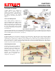
CHAPTER 1 INTRODUCTION EtherStation (Client) Mode When the 195C/M is configured in the EtherStation mode and attached to a single Ethernet Device, the Model 195C/M will emulate a wireless card in functionality for communication as a mobile client. The 195C/M will seamless roam under the radio canopy of Access Points and can provide wireless communication for mobile Ethernet devices such as vehicles, forklifts, cranes, etc (Figures 2&3).
CHAPTER 2 STARTING OUT OVERVIEW There are three main phases to prepare the ESTeem 195C/M for operation in a wireless network: Phase 1 - Determine the correct mode of operation for the ESTeem in the wireless network. The ESTeem 195C/M is a sophisticated networking device that can be configured for multiple modes of operation. Determining the correct mode of operation for the ESTeem 195C/M is the first step.
CHAPTER 2 STARTING OUT Note: Your accessory model numbers may vary from the above, but you will need to locate each of above items to continue configuration.
CHAPTER 2 STARTING OUT MODEL 195C/M HARDWARE CONFIGURATION The following steps should be completed to begin configuration of the ESTeem Model 195C/M: Technical Tips: 1. Connect the antenna to the TNC connection on the ESTeem Model 195C/M (Figure 1). 2. Connect the power supply and Ethernet cable to the ESTeem and proceed to Chapter 3 to begin programming. 1. Configure the Model 195C/M prior to mounting. 2. Attach antenna to the Model 195C/M before powering up.
CHAPTER 3 EXAMPLE APPLICATIONS MODES OF OPERATION The ESTeem Model 195C/M is a sophisticated wireless networking device that can be configured for multiple modes of operation. Determining the correct mode of operation for the ESTeem is the first step in creating a reliable wireless network. This chapter will explain each mode of operation, provide example applications and detailed programming information for each mode. Please review the following modes of operations.
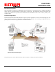
CHAPTER 3 EXAMPLE APPLICATIONS Figure 2: Ethernet Bridge with Repeater Figure 3: Multipoint Bridge with Mesh Networking Revised: 1 Oct 13 3-2 EST P/N AA107-195CM
CHAPTER 3 EXAMPLE APPLICATIONS Router Modes (AP Router and AP Masquerade) The ESTeem 195C/M can be configured as a network router or network firewall between the Ethernet LAN connection and the wireless network of remote locations. The router modes are used to limit the network traffic from a busy Ethernet network connection to only those specific IP address used on the wireless network (see Figure 4).
CHAPTER 3 EXAMPLE APPLICATIONS Mobile Client Modes (EtherStation, Station Router or Station Masquerade) The ESTeem 195C/M can also be configured to function as a mobile client. The client modes allow the 195C/M to seamlessly roam between fixed Access Points. The client modes will allow mobile Ethernet devices to connect to each other or to an Ethernet LAN through the fixed AP (Figure 5). The EtherStation mode is used to connect a single Ethernet device to the ESTeem 195C/M.
CHAPTER 3 EXAMPLE APPLICATIONS PROGRAMMING EXAMPLES Once the mode of operation for the ESTeem has been determined, you are now ready to program the Model 195C/M for use. ESTeem has created a simplified network programming utility call the ESTeem Network Configuration (ENC) Utility. This ENC Utility will be used in all the following programming examples.
CHAPTER 3 EXAMPLE APPLICATIONS Figure 11: Main Office ESTeem 195C/M 3. To change the name of the ESTeem 195C/M from the WLAN MAC address to “Main Office” (or any other location name) to match the example configuration, Right-Mouse click on the ESTeem icon and select Change>Change Modem ID (Figure 12). Enter “Main Office” in the pop-up window and select OK. 4. Duplicate the above procedure for each ESTeem 195C/M added to the network.
CHAPTER 3 EXAMPLE APPLICATIONS Ethernet Bridge Mode Example 1 (Figure 1) Point to Point Ethernet Bridge (2) ESTeem Model 195C/M Serial Numbers: E-14000 (Main Office) and E-14001 (Remote Office) 1. Add the two ESTeem Model 195C/Ms to the network using the above procedure. Once both ESTeem 195C/Ms are on the configuration page, create a wireless link by clinking on one of the two connection boxes and dragging a line to the other modem (Figure 13). 5.
CHAPTER 3 EXAMPLE APPLICATIONS Ethernet Bridge Mode Example 2 (Figure 2) Point to Point with Repeater Ethernet Bridge (3) ESTeem Model 195C/M Serial Numbers: E-14000 (Main Office) E-14001 (Remote Office) E-14002 (Repeater) 1. Using the above procedure, enter the three ESTeem 195C/Ms into the ENC Utility. Your layout should appear like Figure 14. 2. Move the ESTeem 195C/M icons on the screen to simulate the layout of the diagram.
CHAPTER 3 EXAMPLE APPLICATIONS Ethernet Bridge Mode Example 3 (Figure 3) Point to Multipoint with Mesh Repeater Links (6) ESTeem Model 195C/M Serial Numbers: E-14000 (Main Office) E-14001 (Remote Office) E-14002 (Repeater) E-14003 (Remote Site 1) E-14004 (Remote Site 2) E-14005 (Remote Site 3) 1. Using the above procedure for adding ESTeem Model 195C/Ms, add the six ESTeem 195C/Ms for this example and rename by location. Your layout should appear like Figure 16. 2.
CHAPTER 3 EXAMPLE APPLICATIONS Figure 16: Backup Link Configuration in the repeater Mesh configuration (Figure 17). For detailed instruction on Mesh network configuration, refer to Chapter 7 of this User’s Manual. 4. Verify all ESTeem modems are connected to the same switch as the computer running the ENC Utility and send the configuration to all modems at the same time by selecting ESTeem>ESTeem Configuration>Send Configuration to All ESTeems.
CHAPTER 3 EXAMPLE APPLICATIONS Ethernet Router Mode Example (Figure 4) Point to Multipoint Router Mode (4) ESTeem Model 195C/M Serial Numbers: E-14000 (Router at Network) E-14001 (Remote Site 1) E-14002 (Remote Site 2) E-14003 (Remote Site 3) 1. Using the above procedure for adding ESTeem Model 195C/Ms, add the four ESTeem 195C/Ms for this example and rename by location. Your layout should appear like Figure 18. 2. Move the ESTeem 195C/M icons on the screen to simulate the layout of the diagram.
CHAPTER 3 EXAMPLE APPLICATIONS 3. By default, the ENC Utility sets all ESTeem modems in AP Bridge mode. To change the Plant Router ESTeem to AP Router mode, doubleclick on the icon to bring up the ESTeem Summary window and press the Edit button (Figure 20). 4. Change the Mode of Operation from AP Bridge to AP Router (or Masquerade if desired) and press the Next button at the bottom of the window (Figure 21). Figure 20: ESTeem Summary Page Figure 21: AP Router Configuration 5.
CHAPTER 3 EXAMPLE APPLICATIONS Mobile Client Mode Example (Figure 5) EtherStation, Station Router and Station Masquerade Modes (3) ESTeem Model 195C/M Serial Numbers: E-14000 (EtherStation) E-14001 (Station Router) E-14002 (Station Masquerade) Setting the ESTeem for Mobile Client (station) mode with the ENC Utility is different than the Bridge/Router or Access Point (AP) modes. ESTeem modems configured in as a Mobile Client will not link with a specific fixed modem; but will roam between any 802.
CHAPTER 3 EXAMPLE APPLICATIONS Station Router and Station Masquerade 6. To configure the two other modems, double-click on their icons to bring up the ESTeem Summary window and press the Edit button (Figure 20). 7. Select Station Router for E-14001 and Station Masquerade for E-14002 in the Mode of Operation (Figure 26). Press the Next button at the bottom of the window to continue. 8.
CHAPTER 3 EXAMPLE APPLICATIONS ROUTER ADDRESSING EXAMPLES The following are examples of the IP addressing and subnets required for the ESTeem Router modes.
CHAPTER 3 EXAMPLE APPLICATIONS Stand-Alone Access Point Router and Single Station Router Computer IP Address = 172.17.1.1 Netmask = 255.255.0.0 Default Route = 172.17.1.6 ESTeem 195C/M in Access Point Router Mode Ethernet IP Address = 172.17.1.6 Wireless IP Address 172.16.1.6 Netmask = 255.255.0.0 Default Route = 172.17.1.6 Note: Wireless Networks and Station Devices Must Be on Separate Subnets Static Routes Routes for 172.18.0.0 network use gateway 172.16.2.
CHAPTER 3 EXAMPLE APPLICATIONS Stand-Alone Access Point Router with Multiple Station Routers Figure 29: Complete Router Addressing Example Revised: 1 Oct 13 3-17 EST P/N AA107-195CM
CHAPTER 4 UTILITIES & FEATURES ESTeem Network Configuration Utility (ENC) The ESTeem Network Configuration (ENC) Utility is a software program designed to greatly simplify the configuration of your ESTeem Model 195C/M wireless Ethernet network. The ENC Utility will allow graphical, point-and-click configuration of your network routing, then configure each ESTeem wireless modem for the network as designed (Figure 1).
CHAPTER 4 UTILITIES & FEATURES ESTEEM DISCOVERY UTILITY The ESTeem Discovery Utility will allow you to configure the IP address on the Model 195C/M to match your network regardless of its current IP subnet. This utility will also allow you to update the software in the 195C/M and open the web configuration for that wireless modem. Installation To install the Discovery Utility on your computer, insert the Resource Disk in your CD drive.
CHAPTER 4 UTILITIES & FEATURES Note: This program is saved in a compressed file format. 3. Double click on the 195C/MDiscoverySetup.exe file listed in the window to install the program. Figure 4: Discovery Program Main Page 4. Connect the Model 195C/M to your computer either directly to the Ethernet card or through a HUB/Switch using a CAT-5e Ethernet cable. The Ethernet port on the 195C/M supports Auto-Negotiation, so either a patch cable or crossover cable will work.
CHAPTER 4 UTILITIES & FEATURES Firmware Updates To update firmware on any ESTeem Model 195 that is shown on the Discovery program, “right-mouse” click on the 195’s MAC address and select Update from the menu (Figure 6). Once you locate the update file, select the Open button and the 195 will update, validate and then reboot with the updated operating system.
CHAPTER 4 UTILITIES & FEATURES ETHERSTATION STATUS PROGRAM When configured for EtherStation mode, the Web Configuration Manger is turned off. To gather information from the 195C/M on Access Point, link status and received signal strength you will need to install the ESTeem 195C/M Status Utility. The EtherStation Status Utility version 2.0.0.0 or greater provides a new feature that will automatically program the connected ESTeem 195C/M to match up with the computer running the software.
CHAPTER 4 UTILITIES & FEATURES SETTING LOCAL TIME The ESTeem Model 195C/M will be shipped from the factory with the internal real-time clock set to Pacific Time. To change the clock settings to the local time for accurate log file entries: 1. Select Advanced from the top Menu, then Wireless LAN Settings>wlan0 device. Press the Next button (Figure 9). 2. Select Global Settings>Set System Time from the menu and press the Next button to continue. 3.
CHAPTER 4 UTILITIES & FEATURES CONFIGURING TIME SERVER Enabling NTP time synchronization services on the ESTeem 195C/M will allow usage of time services from upstream services to keep the time on the system accurate. To allow time synchronization, the Model 195C/M must be configured with the NTP Daemon enabled and the appropriate IP address of the upstream network NTP server. 1. Select Advanced from the menu items and Global Variables (Figure 11). Figure 11: Advanced Settings Menu 2.
CHAPTER 4 UTILITIES & FEATURES 3. The NTP daemon is enabled by selecting YES for NTP ENABLE (Figure 12). When enabled, the NTP daemon will use time services from upstream services to keep the time on this system accurate. 4. Next, the NTP SERVICE ENABLE should be configured to “YES,” if you want to allow the system to provide NTP service for clients wishing time synchronization (Figure 12). Figure 12: NTP Settings 5.
CHAPTER 4 UTILITIES & FEATURES 6. Once configuration is complete, press the Return to Advanced button. 7. To complete the configuration, select “Commit and Reboot.” The ESTeem 195C/M will now commit the configuration changes and reboot.
CHAPTER 4 UTILITIES & FEATURES Simple Network Management Protocol (SNMP) The ESTeem 195C/M supports SNMP Version 1 (SNMPv1) and Version 2 (SNMPv2c) protocol. This protocol enables any SNMP server to view the status of the wireless network while the system is in operation.
CHAPTER 4 UTILITIES & FEATURES [[ peer table entry ]] EST-MIB::wirelessPeersNumber.0 wlan device Peer MAC Address isRepeater? isAP? isAssocSta? isAdhoc? Frequency current rate set last rx signal last rx noise BSSID SSID isValid? EST-MIB::wirelessPeerTable.1.pDevice.1 EST-MIB::wirelessPeerTable.1.pMacAddr.1 EST-MIB::wirelessPeerTable.1.pRepeater.1 EST-MIB::wirelessPeerTable.1.pAP.1 EST-MIB::wirelessPeerTable.1.pAssoc.1 EST-MIB::wirelessPeerTable.1.pAdhoc.1 EST-MIB::wirelessPeerTable.1.pFreq.
CHAPTER 6 SERIAL APPLICATIONS USING THE USB PROGRAMMING PORT Any terminal emulation program can be used for this configuration of the ESTeem 195C/M through the USB port. Most Windows users will probably use either Hyper Terminal or the Terminal Emulation in the ESTeem Utility program. Programming Using the USB Port 1.
CHAPTER 6 SERIAL APPLICATIONS 9. To set the IP address in the ESTeem 195C/M, type the letter “A” and press the Enter key. Enter the value for the IP address, Netmask and default route pressing the Enter key after each entry. Figure 2: RS-232 Welcome Screen 10. After the basic parameters have been entered into the Model 195C/M you will need to commit the changes to the Model 195C/M (Figure 3). Press the C key and then Enter. The changes will be saved to flash memory.
CHAPTER 6 SERIAL APPLICATIONS USING THE RS-232 DATA PORT The ESTeem 195C/M has a serial data port that can provide RS-232 communication between two or more serial devices using the wireless broadband link. The serial data is encapsulated and transferred as a standard Ethernet packet over an operating 195C/M wireless Ethernet system. The configuration for a serial 195C/M network will be the same as an Ethernet or a serial (RS-232) based communication network.
CHAPTER 6 SERIAL APPLICATIONS Figure 5: Serial Configuration Screen Data Bits Select the number of data bits on the RS-232 connection to match your serial device. Stop Bits Select the number of stop bits on the RS-232 connection to match your serial device. Parity Select the parity of the RS-232 connection to match your serial device.
CHAPTER 6 SERIAL APPLICATIONS Flow Control Select the type of data flow control used on the RS-232 connection. The ESTeem can support Hardware flow control (RTS/CTS control lines) or Software Flow Control (XON/XOFF). Select None if no serial flow control is necessary. Maximum Bridge Links for Multicast Packets This value sets the maximum number of Ethernet bridge links that the multicast packets will be sent through when used in a multipoint system.
CHAPTER 6 SERIAL APPLICATIONS Li ne -o f-S ig ht P th Pa RS-232 Data Access Point Bridge with Repeater Mode at h ht ig f- S -o ne Li Access Point Bridge with Repeater Mode Line-of-Sight Path Remote Site Remote PLC Access Point Bridge with Repeater Mode RS-232 Data Lin e-o f- Sig ht P ath Repeater Path ight -of-S Line Remote Site & Repeater RS-232 Data Access Point Bridge with Repeater Mode NOTE: Repeater may be standalone or attached to a network or device.
CHAPTER 7 REPEATING FEATURES When programmed in any of the three Access Point (AP) Repeater Modes, the Model 195C/M will create a wireless network with other Model 195C/M units in radio range that are programmed in the AP Repeater Peer table during setup. This feature adds the increased functionality of repeaters to the typical Ethernet Bridge configuration.
CHAPTER 7 REPEATING FEATURES Configuration The configuration of the repeater paths is completed during setup of the Access Point modes. All three Access Point modes support repeating and Meshing features. The Mesh network configuration using the ESTeem Network Configuration (ENC) Utility is shown in detail in Chapter 3 of this User’s Manual. Figure 2: Repeater Configuration Example You can also configure the Mesh networking directly through the web configuration setup (Chapter 5).
CHAPTER 7 REPEATING FEATURES RAPID SPANNING TREE PROTOCOL (RSTP) The ESTeem Model 195C/M uses Rapid Spanning Tree Protocol (RSTP - IEEE 802.1d) to determine the radio routing structure of the wireless network. This RSTP functions the same as standard Spanning Tree Protocol (STP) listed below, but the network recovery is three times faster. If the 195C/M is used in a network that has any older STP only modems, the entire network will be STP.