
User's Manual
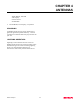
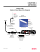
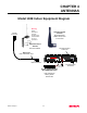
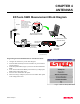
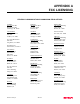
Table Of Contents

CHAPTER 4
ANTENNAS
Revised: 10 May 01 4-6
ESTeem SWR Measurement Block Diagram
Programming the ESTeem Model 192E For SWR Measurements
1.
Configure the hardware as per the above diagram.
2.
Install the ESTeem Utility on the PC hard drive as per instructions
with the software.
3.
From Utility Main Menu (Figure 1) select the Terminal Emulation
Mode.
4.
In the Terminal Emulation Mode press the Enter key to display the
Model 192E configuration menu.
5.
Select the Turn Transmitter ON option.
6.
When the testing is completed, select Turn Transmitter OFF option
on the configuration menu.
Figure 1: ESTeem Utility Main Menu
N Male
Connector
N Male
Connector
TNC-R Male
Connector
Antenna
2 Pin Molex
Connector
RS-232C Interface Cable
(EST P/N AA062)
N Male
Connector
SWR Meter
RG-8 Cable
(EST P/N AA230)
12 VDC Power Supply
(EST P/N AA174)
S/ N :T/E
TX
RX
PW R
IR
Po r t
Phone
Model 192S
Antenna
12 VD C
RESET
ESTeem Model 192 Utility
Software Windows Version
Warning
Omni-directional antenna
should not be located within
20 cm of personnel
High gain directional
antenna’s main beam should
not be pointed in close
proximity of personnel.