ESTEEM USERS MANUAL for MODEL 192E May 2001 Electronic Systems Technology (EST) copyrights this manual and the firmware described in it, with all rights reserved. Under the copyright laws, this manual or the firmware internal to the ESTeem unit may not be copied, in whole or part, without the written consent of EST. Under the law, copying includes translating into another language.
PRODUCT WARRANTY Electronic Systems Technology, Inc., (hereinafter EST) expressly warrants its products as free of manufacturing defects for a period of one year from the date of sale to first user/customer.
TABLE OF CONTENTS CHAPTER 1 - STARTING OUT CHAPTER 4 - ANTENNAS Overview............................................................. 1-2 Antenna and Cable Configurations.......................4-2 Hardware Layout ................................................. 1-2 Weather Proofing Coaxial Connectors..................4-2 Installing ESTeem Utility Software – Windows 95/98/NT ............................................. 1-2 Grounding ...........................................................
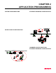
CHAPTER 2 APPLICATION PROGRAMMING SYSTEM CONFIGURATIONS ETHERNET BRIDGING CONFIGURATION LAN Bridging ACCESS POINT CONFIGURATION Ethernet Wired LAN Digi-Repeating 192E 192E 192E Ethernet Wired LAN HMI Terminal Programming Terminal 192E Wireless Access Point Remote PLC Remote PLC Point to Multi-Point Wireless Network COMBINED ACCESS POINT AND ETHERNET BRIDGING CONFIGURATION Ethernet Wired LAN 192E 192E Model WLANC11 Wireless LAN Card Mobile Wireless Network With Overlap Coverage
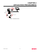
CHAPTER 2 APPLICATION PROGRAMMING LAN Bridging Ethernet Wired LAN Digi-Repeating 192E 192E 192E Ethernet Wired LAN Ethernet Hub 10BASE-T Model WLANC11 Wireless LAN Card 192E Mobile Wireless Network Figure 3: Combination Network Revised: 10 May 01 2-3
CHAPTER 2 APPLICATION PROGRAMMING SYSTEM CONFIGURATIONS ACCESS POINT CONFIGURATION ETHERNET BRIDGING CONFIGURATION COMBINED ACCESS POINT AND ETHERNET BRIDGING CONFIGURATION
CHAPTER 2 APPLICATION PROGRAMMING SYSTEM CONFIGURATIONS ETHERNET BRIDGING CONFIGURATION The ESTeem Model 192E can be used in a variety of network system configurations. The ESTeem can stand alone as the center of a wireless infrastructure, can provide access from your wireless network to your wired LAN, or bridge between Ethernet segments on your network. The Ethernet Bridging network allows the Model 192E modems to provide links between two or more Ethernet segments on a network.
CHAPTER 2 APPLICATION PROGRAMMING LAN Bridging Ethernet Wired LAN Digi-Repeating 192E 192E 192E Ethernet Wired LAN Ethernet Hub 10BASE-T Model WLANC11 Wireless LAN Card 192E Mobile Wireless Network Figure 3: Combination Network Revised: 10 May 01 2-3
CHAPTER 3 INTERFACING SERIAL INTERFACE CONFIGURATION RS-232 PORT PINOUT TABLE ETHERNET INTERFACE
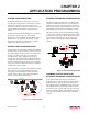
CHAPTER 3 INTERFACING SERIAL INTERFACE CONFIGURATION ETHERNET INTERFACE The ESTeem Model 192E has a standard RS-232C, 9-pin Female connector for interfacing directly with the serial port on the computer. Use ESTeem part number AA062 to interface the Model 192E with a 9-pin serial port on a computer. The ESTeem Model 192E’s Ethernet Port is configured to directly interface with an Ethernet HUB using a straight through 10BaseT cable.
CHAPTER 4 ANTENNAS ANTENNA AND CABLE CONFIGURATIONS WEATHER PROOFING COAXIAL CONNECTORS GROUNDING LIGHTINING ARRESTORS MODEL 192E TYPICAL OUTDOOR ANTENNA INSTALLATION DIAGRAM MODEL 192E TYPICAL INDOOR ANTENNA INSTALLATION DIAGRAMS ESTEEM SWR MEASUREMENT BLOCK DIAGRAM
CHAPTER 4 ANTENNAS ANTENNA AND CABLE CONFIGURATIONS COAXIAL CABLES To minimize signal loss, the overall length of the coaxial cable should be as short as possible. To avoid corrosion select coaxial cable manufacturers with tinned copper braid, where possible. Listed below are representative cable losses in db/100 ft at the 2.4 GHz frequency range: EST offers three (3) different types of antennas for both indoor and outdoor configurations. Part Number: AA01S Omni Directional Rubber Duck Antenna.
CHAPTER 4 ANTENNAS VYNIL-MASTIC, P/N 2200 3-M Company Customer Service 512-984-1800 3. SCOTCHKOTE, 3-M Company, or equivalent. GROUNDING All building mount antennas require attachment to a good earth ground for optimum efficiency. Contact a reputable local communications shop for procedures for your area. LIGHTNING ARRESTORS Lightning arrestors should be used on all external building mount antennas for personal protection and to minimize damage to the transceiver during lightning storms.
CHAPTER 4 ANTENNAS Model 192E Outdoor Fixed Base Site Diagram Warning Omnidirectional antenna should not be located within 20 cm of personnel. ANTENNA RECOMMENDATIONS Warning N Male Connector High gain directional antenna’s main beam should not be pointed in close proximity of personnel. Omni-Directional Antenna EST P/N AA20S. Heliax Feedline EST P/N AA236, 50 ft. Directional Antenna EST P/N AA202S. RG-8 Coax EST P/N AA230, 2 ft.
CHAPTER 4 ANTENNAS Model 192E Indoor Equipment Diagram Warning N Male Connector Omnidirectional antenna should not be located within 20 cm of personnel. RE SET Omni-Directional Antenna EST P/N AA01S. Rubber duck, back of set mount Omni-Directional Antenna EST P/N AA20S. RS-232 Interface Connector RE SET RG-8 Coax EST P/N AA230, 25 ft.
CHAPTER 4 ANTENNAS ESTeem SWR Measurement Block Diagram Warning Omni-directional antenna should not be located within 20 cm of personnel Antenna High gain directional antenna’s main beam should not be pointed in close proximity of personnel.
APPENDICES APPENDIX “A” FCC INFORMATION (USA Only) APPENDIX “B” SPECIFICATIONS ESTeem Specifications Antenna Specifications
APPENDIX A FCC LICENSING INFORMATION TO USERS This equipment complies with FCC Part 15.
APPENDIX A FCC LICENSING FEDERAL COMMUNICATIONS COMMISSION FIELD OFFICES ALASKA 1011 E. Tudor Rd. Rm 240 Box 2955 Anchorage, AK 99510 HAWAII 300 Almoana Blvd. P.O. Box 50023 Honolulu, HI NEW YORK 1307 Federal Building 111 W. Huron Buffalo, NY 14202 CALIFORNIA 7840 El Cajon Blvd Suite 405 La Mesa, CA 92041 ILLINOIS 3935 Federal Bldg 230 S. Dearborn Chicago, IL 60604 201 Varick Street New York, NY 10014 3711 Long Beach Blvd Suite 501 Long Beach, CA 90807 LOUISIANA 1009 Edw Hebert Bldg.
APPENDIX B SPECIFICATIONS Model 192E Specifications LED INDICATORS RF DATA RATE SIZE • • • Power On Receiver Carrier Detect Transmitter Enable • • I/O – CONNECTORS • • • • • • • • • • RS-232C - 9 Pin Sub D Female RJ-45 10BaseT Connection Antenna Output – TNC-R Input Power - 2 Pin Molex Female 1-11 Mbps RF data rate TRANSMITTER 1 Watt RF output 100% duty cycle 50 ohms output impedance Protocol activated keying 10 µsec typical latency Direct sequence spread spectrum • • • • • • RS-232 Asynchron
APPENDIX B SPECIFICATIONS Model 192S Antennas Model No: Antenna Type: Applications: Frequency: Polarization: Impedance: Gain: VSWR: Front To Back Ratio: Horizontal Beamwidth: Vertical Beamwidth: Antenna Material: Mounting Hardware: Antenna Connector: Antenna Envelope: Weight: AA01S Omni-Directional, right angle rubber duck, ½ wave Back of ESTeem Model 192S mount. 2400 to 2485 MHz Vertical 50 ohms 3 dBd < 1.5 n/a n/a n/a Rubber duct whip. n/a TNC-R Male 4 in. length by 1.5 in width .08 lbs. 4 in. 1.5 in.
APPENDIX B SPECIFICATIONS Model 192S Antennas Model No: Antenna Type: Applications: Frequency: Polarization: Impedance: Gain: VSWR: Front To Back Ratio: Horizontal Beamwidth: Vertical Beamwidth: Antenna Material: Mounting Hardware: Antenna Connector: Maximum Power Input: Antenna Envelope: Windload (RWV): Wind Load ½ in. Ice: Wind Surface Area: Weight: Revised: 11 May 01 AA202S Directional, 15 element yagi in sealed UV stable radome Fixed base. 2400 to 2500 MHz Linear 50 ohms 13.9 dBd < 1.