
User Manual
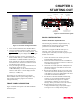
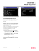
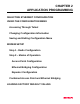
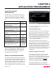
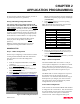
Table Of Contents

CHAPTER 1
STARTING OUT
Revised: 2 Oct 01 1-3
2. Select Terminal Emulation from the Main Menu.
3. Once the Terminal Emulation is loaded, select the
Terminal Setup from the menu and press Ports. You
should see the serial port configuration menu (Figure
3).
4. Select the serial port you have connected to the
ESTeem Model 192E (i.e. COM1 would be 1), set
the Baud Rate to 38400, Data Bits to 8, Parity to
None, Stop Bits to 1 and leave both the Hardware
and Software flow control boxes unchecked. Press
the OK button when complete.
5. Verify the settings in the upper left hand corner of
the Terminal window are set to
COM1:38400,N,8,1). If the communications port
number is other than 1 it will be displayed as the
number (i.e. COM2, etc.).
The software is now configured for accessing the
ESTeem Model 192E for system configuration. Any
other terminal emulation program will need to be
configured similarly.
FRONT PANEL DESCRIPTION
Figure 4 contains a description of the ESTeem Model
192E front panel.
BASIC CONFIGURATION
Connect and Power Up the ESTeem
The following steps should be completed before any
modifications are made to the network operating
parameters for the ESTeem Model 192E.
Note: Plan to configure the Model 192E prior to
mounting. Some of the following steps, such as
connecting the serial cable, are easier to perform if the
ESTeem is accessible.
1. Connect the antenna to the antenna port on the
ESTeem Model 192E (Figure 4).
2. Connect the Ethernet cable from the wired 10BaseT
Ethernet LAN to the Ethernet connector on the front
of the ESTeem (Figure 4).
3. Connect the serial cable (EST P/N: AA062) between
the RS-232 connector on the ESTeem to the serial
port on the computer.
4. Plug the ESTeem Model AA174 power supply into a
wall socket and connect the Molex power connector
to the ESTeem. The power light (PWR) on the front
of the ESTeem should be illuminated.
5. You should see the ESTeem Model 192E booting
sequence on your Terminal Emulation program.
Once the ESTeem boot sequence is complete
(approximately 1 minute) you will receive the
message “Please press Enter to active this console.”
6. Press the Enter key and you will be at the
Configuration Menu login prompt (192E login:).
See Figure 5 for an example of this prompt.
Figure 3: Serial Port Configuration Menu
Antenna Connector
(TNC-R)
12 VDC Input
Power Connector
(2 Pin Molex)
Reset Switch
RS-232
Input/Output Connector
(9 Pin DB Connector)
RJ-45 10BaseT
Ethernet Port
Power LED
Transmit LED
Receive LED
T/E LED
T/E
Figure 4: Front Panel Description