
User Manual
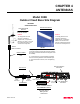
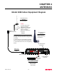
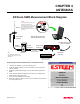
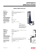
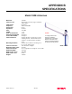
Table Of Contents

CHAPTER 4
ANTENNAS
Revised: 15 Oct 01 4-6
ESTeem SWR Measurement Block Diagram
N Male
Connector
N Male
Connector
Antenna
2 Pin Molex
Connector
RS-232C Interface Cable
(EST P/N AA062)
SWR Meter
RG-8 Cable
(EST P/N AA230)
12 VDC Power Supply
(EST P/N AA174)
S/N:T/E
TX
RX
PWR
IR
Port
Phone
Model 192S
Antenna
12 VDC
RESET
ESTeem Model 192 Utility
Software Windows Version
TNC-R Male
Connector
TNC-R Male
Connector
Caution
To comply with the FCC exposure
compliance requirements, a
separation distance of at least 7 cm
for an omni-directional and 19 cm for
a directional antenna must be
maintained between the antenna and
all persons.
Note
The cables listed above are only
available with the purchase of an
SWR Meter.
Programming the ESTeem Model 192E For SWR Measurements
1. Configure the hardware as per the above diagram.
2. Install the ESTeem Utility on the PC hard drive as per instructions
with the software.
3. From Utility Main Menu (Figure 1) select the Terminal Emulation
Mode.
4. In the Terminal Emulation Mode press the Enter key to display the
Model 192E configuration menu.
5. Select the Turn Transmitter ON option.
6. When the testing is completed, select Turn Transmitter OFF option on
the configuration menu.
Figure 1: ESTeem Utility Main Menu