
User Manual
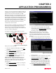
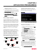
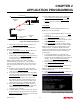
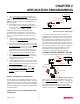
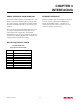
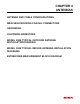
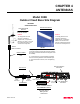
Table Of Contents

CHAPTER 4
ANTENNAS
Revised: 15 Oct 01 4-2
ANTENNA AND CABLE
CONFIGURATIONS
Warning: Only the tested cable lengths and antennas
provided by EST meet the FCC maximum peak output
power requirements. Any other combination of
antennas or coax cables is not authorized.
EST offers three (3) different types of antennas for both
indoor and outdoor configurations.
Part Number: AA01S
Omni Directional Rubber Duck Antenna.
Unity Gain
Directly mounts to antenna port
Part Number: AA20S
Omni Directional Building Mount Antenna
5 dBd gain
Uses either 25’ RG-8 Cable (Indoor) or
50’ Heliax Cable (Outdoor)
Part Number: AA202S* (Point-to-point ONLY)
Directional Building Mount Antenna
13.9 dBd gain
50’ Heliax Cable (Outdoor) with Lightning Arrestor
(EST P/N: AA164) and RG-8 Patch Cable
Outdoor Fixed Base Configuration
AA20S or AA202S Antenna
Lightning Protection
50’ Heliax Cable
Indoor Configuration
AA20S or AA202S Antenna
25’ RG-8 Cable
Warning: Only pre-made coax cables from the factory
used in conjunction with either the AA20S
omni-directional or AA202S directional
antenna meet all FCC Section 15.247(b)
EIRP maximum power requirements.
*Use of the AA202S, directional antenna
is limited to fixed point to point
applications only. In accordance FCC
Section 15.247(b)iii, the operator or
installer is responsible for ensuring the
systems is used exclusively for fixed, point-
to-point applications.
COAXIAL CABLES
The 25’ length of RG-8 coax cable and the 50’ length of
Heliax cable are the minimum cable lengths allowed for
use the above antennas. Listed below are representative
cable losses in db/100 ft at the 2.4 GHz frequency range:
Frequency (MHz) RG-8 ½” Heliax
---------------------------------------------------------------------
2400-2462 - 10.0 - 3.74
In a severe noise environment it may be necessary to use
a double shield type of coax cable such as RG-214/U in
place of the RG-8. This cable must be purchased from
the factory to meet FCC requirements.
Note: A -3 dB loss means you have lost 1/2 of your
signal. A +3 dB gain means you have doubled
(x2) your signal.
WEATHER PROOFING COAX
CONNECTIONS
1. Coat the threads of the connectors with silicone
lubricant prior to assembly (See Note 1) and hand
tighten. Care should be taken not to get any
lubricant on the center conductor.
2. Wrap the connector assembly with a vapor barrier
patch for weather proofing (See Note 2), ensuring to
overlap onto the coax cable approximately 1 1/2
inches.
3. Apply an electrical coating (sealing agent) over the
vapor barrier patch for added protection (See Note
3).
Notes:
1. Dow Corning RTV-3140 or equivalent.
2. Suggested vendors:
VAPOR-WRAP
Decibel Products
3184 Quebec St.
Dallas, TX 75356
214-631-0310
VYNIL-MASTIC, P/N 2200
3-M Company
Customer Service
512-984-1800
3. SCOTCHKOTE, 3-M Company, or equivalent.