ESTEEM USERS MANUAL for MODEL 192E October 2001 Electronic Systems Technology (EST) copyrights this manual and the firmware described in it, with all rights reserved. Under the copyright laws, this manual or the firmware internal to the ESTeem unit may not be copied, in whole or part, without the written consent of EST. Under the law, copying includes translating into another language.
PRODUCT WARRANTY Electronic Systems Technology, Inc., (hereinafter EST) expressly warrants its products as free of manufacturing defects for a period of one year from the date of sale to first user/customer.
TABLE OF CONTENTS CHAPTER 1 - STARTING OUT Repeater Configuration ....................................... 2-6 Overview ............................................................. 1-2 Combined Access Point and Bridging.................. 2-6 Hardware Layout ................................................. 1-2 Loading Factory Default Values .......................... 2-7 Installing ESTeem Utility Software – Windows 95/98/NT.............................................. 1-2 Running The Program .......
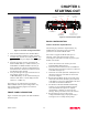
CHAPTER 1 STARTING OUT OVERVIEW HARDWARE LAYOUT INSTALLING SOFTWARE Installing ESTeem Utility Software Running The Program FRONT PANEL DESCRIPTION BASIC CONFIGURATION Connect and Power Up the ESTeem Opening the Configuration Menu
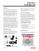
CHAPTER 1 STARTING OUT OVERVIEW Caution: Your ESTeem hardware may have antennas other than the AA01S listed in Figure 1, but you must have an antenna connected to the antenna port before applying power to the unit. The ESTeem Model 192E is a wireless LAN transceiver that can be configured as the center point of a standalone wireless network, connection point between wireless and wired network (Access Point) or a bridge between Ethernet segments.
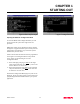
CHAPTER 1 STARTING OUT Transmit LED T/E LED RJ-45 10BaseT Ethernet Port Receive LED T/E Reset Switch Power LED Antenna Connector (TNC-R) 12 VDC Input Power Connector (2 Pin Molex) RS-232 Input/Output Connector (9 Pin DB Connector) Figure 4: Front Panel Description BASIC CONFIGURATION Connect and Power Up the ESTeem The following steps should be completed before any modifications are made to the network operating parameters for the ESTeem Model 192E. Figure 3: Serial Port Configuration Menu 2. 3.
CHAPTER 1 STARTING OUT Figure 6: Configuration Menu Figure 5: Boot Prompt Example Opening the ESTeem Configuration Menu To enter the Model 192E Configuration Menu you will need to log into the system with a login name and password. Note: These values can be changed from factory default through the Configuration Menu. If this not the first time configuration of the ESTeem, see you network systems administrator for these values.
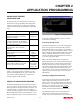
CHAPTER 2 APPLICATION PROGRAMMING SELECTING ETHERNET CONFIGURATION USING THE CONFIGURATION MENU Accessing Through Telnet Changing Configuration Information Saving and Exiting Configuration Menu MODEM SETUP Step 1 - Radio Configuration Step 2 – Modes of Operation Access Point Configuration Ethernet Bridging Configuration Repeater Configuration Combined Access Point and Ethernet Bridging LOADING FACTORY DEFAULT VALUES
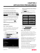
CHAPTER 2 APPLICATION PROGRAMMING SELECTING ETHERNET CONFIGURATION To begin setup of your wireless Ethernet network you must first select the type of Model 192E configuration required. The following are examples of networking requirements and the type of configuration required for each: Networking Requirements Link 802.
CHAPTER 2 APPLICATION PROGRAMMING Mbps) are listed, the ESTeem will scale through the baud rates as required by signal quality and strength (recommended). 5. Select Channel (3) to set the operating frequency of the ESTeem. Note: All ESTeems that communicate with each other MUST be set to the same channel number. the previous menu without making changes, press the X key followed by the Enter key (X
CHAPTER 2 APPLICATION PROGRAMMING network, all wireless cards (ESTeem Model WLANC11) communicate only with the Access Point that serves the Wireless Local Area Network (WLAN) as a HUB. Multiple Access Points can be configured in the network to extend the coverage area of the wireless cards. The wireless cards will automatically change between Access Points (Roam) as long as they are all configured with the same SSID and Wired Equivalent Privacy (WEP) information.
CHAPTER 2 APPLICATION PROGRAMMING 128bit WEP encryption. If using 40bit WEP encryption, leave at “False”. 11. Load the WEP Key values in sections 4-12. Review all your changes on the screen are correct and select Return to previous menu (X) to return to the Access Point Configuration Menu. 12. If all configurations appear correct, press Load Values and Return to Main Menu (M). 13. Once at the Main Menu, press Save and Apply Changes (7) and Yes (Y) to reboot the ESTeeem.
CHAPTER 2 APPLICATION PROGRAMMING Ethernet Wired LAN 14. If all configurations appear correct, press Load Values and Return to Main Menu (M). 15. Once at the Main Menu, press Save and Apply Changes (7) and Yes to reboot the ESTeeem. Ethernet IP Address (Example) 192.168.1.1 192E - Master Bridge Wireless IP Address (Example) 192.168.2.1 Client Bridge To configure the ESTeem Model 192E as a Client Bridge, please use the following: Wireless IP Address (Example) 192.168.2.0 1.
CHAPTER 2 APPLICATION PROGRAMMING Ethernet Wired LAN 9. Select Current Master IP Address (6) to input the Wireless IP address of the Master Bridge. Note: The Master IP address must match the Wireless IP address of the Master Bridge for the bridging mode to function correctly. 10. If the bridge network is going to be using WEP security codes, press Encryption Settings (7) to enter the Privacy Menu (Figure 5) otherwise leave the setting at “False” and skip to Step 15.
CHAPTER 3 INTERFACING SERIAL INTERFACE CONFIGURATION RS-232 PORT PINOUT TABLE ETHERNET INTERFACE
CHAPTER 3 INTERFACING SERIAL INTERFACE CONFIGURATION ETHERNET INTERFACE The ESTeem Model 192E has a standard RS-232C, 9-pin Female connector for interfacing directly with the serial port on the computer. Use ESTeem part number AA062 to interface the Model 192E with a 9-pin serial port on a computer. The ESTeem Model 192E’s Ethernet Port is configured to directly interface with an Ethernet HUB using a straight through 10BaseT cable.
CHAPTER 4 ANTENNAS ANTENNA AND CABLE CONFIGURATIONS WEATHER PROOFING COAXIAL CONNECTORS GROUNDING LIGHTINING ARRESTORS MODEL 192E TYPICAL OUTDOOR ANTENNA INSTALLATION DIAGRAM MODEL 192E TYPICAL INDOOR ANTENNA INSTALLATION DIAGRAMS ESTEEM SWR MEASUREMENT BLOCK DIAGRAM
CHAPTER 4 ANTENNAS ANTENNA AND CABLE CONFIGURATIONS COAXIAL CABLES The 25’ length of RG-8 coax cable and the 50’ length of Heliax cable are the minimum cable lengths allowed for use the above antennas. Listed below are representative cable losses in db/100 ft at the 2.4 GHz frequency range: Warning: Only the tested cable lengths and antennas provided by EST meet the FCC maximum peak output power requirements. Any other combination of antennas or coax cables is not authorized.
CHAPTER 4 ANTENNAS GROUNDING LIGHTNING ARRESTORS All building mount antennas require attachment to a good earth ground for optimum efficiency. Contact a reputable local communications shop for procedures for your area. Lightning arrestors should be used on all external building mount antennas for personal protection and to minimize damage to the transceiver during lightning storms. The units should be installed as per manufacturers instructions provided with the device.
CHAPTER 4 ANTENNAS Model 192E Outdoor Fixed Base Site Diagram ANTENNA CONFIGURATIONS Directional Antenna Omni-Directional Antenna EST P/N AA202S. EST P/N AA20S. Caution Caution To comply with the FCC exposure compliance requirements, a separation distance of at least 7 cm must be maintained between the antenna and all persons. To comply with the FCC exposure compliance requirements, a separation distance of at least 19 cm must be maintained between the antenna and all persons..
CHAPTER 4 ANTENNAS Model 192E Indoor Equipment Diagram Omni-Directional Antenna EST P/N AA20S. Caution TNC-R Male Connector To comply with the FCC exposure compliance requirements, a separation distance of at least 7 cm must be maintained between the antenna and all persons. NOTES Omni-Directional Antenna RE SET 1. Vapor wrap all external antenna coax connections with vinyl wrap (EST Part No. AA241) and apply Scotchkote Electrical Coating (EST Part No. AA242). EST P/N AA01S.
CHAPTER 4 ANTENNAS ESTeem SWR Measurement Block Diagram Caution Antenna To comply with the FCC exposure compliance requirements, a separation distance of at least 7 cm for an omni-directional and 19 cm for a directional antenna must be maintained between the antenna and all persons.
APPENDICES APPENDIX “A” FCC INFORMATION (USA Only) APPENDIX “B” SPECIFICATIONS ESTeem Specifications Antenna Specifications
APPENDIX A FCC LICENSING INFORMATION TO USERS The ESTeem Model 192E complies with Part 15 of the FCC Rules. Operation is subject to the following two conditions: (1) This device may not cause harmful interference, and (2) this device must accept any interference received, including interference that may cause undesired operation.
APPENDIX A FCC LICENSING FEDERAL COMMUNICATIONS COMMISSION FIELD OFFICES ALASKA 1011 E. Tudor Rd. Rm 240 Box 2955 Anchorage, AK 99510 HAWAII 300 Almoana Blvd. P.O. Box 50023 Honolulu, HI NEW YORK 1307 Federal Building 111 W. Huron Buffalo, NY 14202 CALIFORNIA 7840 El Cajon Blvd Suite 405 La Mesa, CA 92041 ILLINOIS 3935 Federal Bldg 230 S. Dearborn Chicago, IL 60604 201 Varick Street New York, NY 10014 3711 Long Beach Blvd Suite 501 Long Beach, CA 90807 LOUISIANA 1009 Edw Hebert Bldg.
APPENDIX B SPECIFICATIONS Model 192E Specifications LED INDICATORS RF DATA RATE SIZE • • • Power On Receiver Carrier Detect Transmitter Enable • • I/O – CONNECTORS • • • • • • • • • • RS-232C - 9 Pin Sub D Female RJ-45 10BaseT Connection Antenna Output – TNC-R Input Power - 2 Pin Molex Female 1-11 Mbps RF data rate TRANSMITTER 1 Watt RF output 100% duty cycle 50 ohms output impedance Protocol activated keying 10 µsec typical latency Direct sequence spread spectrum • • • • • • RS-232 Asynchron
APPENDIX B SPECIFICATIONS Model 192E Antennas Model No: Antenna Type: Applications: Frequency: Polarization: Impedance: Gain: VSWR: Front To Back Ratio: Horizontal Beamwidth: Vertical Beamwidth: Antenna Material: Mounting Hardware: Antenna Connector: Antenna Envelope: Weight: AA01S Omni-Directional, right angle rubber duck, ½wave Back of ESTeem Model 192S mount. 2400 to 2485 MHz Vertical 50 ohms 2 dBd < 1.5 n/a n/a n/a Rubber duct whip. n/a TNC-R Male 4 in. length by 1.5 in width .08 lbs. 4 in.
APPENDIX B SPECIFICATIONS Model 192E Antennas Model No: Antenna Type: Applications: Frequency: Polarization: Impedance: Gain: VSWR: Front To Back Ratio: Horizontal Beamwidth: Vertical Beamwidth: Antenna Material: Mounting Hardware: Antenna Connector: Maximum Power Input: Antenna Envelope: Windload (RWV): Wind Load ½ in. Ice: Wind Surface Area: Weight: Revised: 15 Oct 01 AA202S Directional, 15 element yagi in sealed UV stable radome Fixed base. 2400 to 2500 MHz Linear 50 ohms 13.9 dBd < 1.