
User's Manual
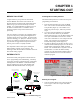
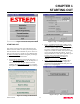
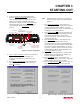
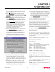
Table Of Contents

CHAPTER 1
STARTING OUT
Revised: 27 Mar 01 1-4
4.
Press the Front Panel Description button and a
window containing the ESTeem Model 192 front
panel will appear (Figure 7). Press any one of the
buttons for a complete description of the item’s
function. For example, press the Power LED button
and the description of the power LED and its use
will be displayed. Press Go To Step 3 button to
proceed.
5.
Step 3 – Serial Connection window will be displayed
(Figure 8). This step will help configure the
computer and the ESTeem to communicate with
each other.
6.
Press Display Cable Diagrams button and all serial
pins to the ESTeem Model 192 will be displayed.
Press OK to continue.
Note: A standard 9-Pin serial port on a computer to
ESTeem interface cable is the ESTeem AA061
(Figure 1).
7.
Press Change Port Settings. This window will
configure the communications port on your computer
to operate with the ESTeem modem. Select the
operating parameters you wish or set to the default of
19,200,N,8,1. Click OK to continue.
8.
Press Set Serial Switches button. This window will
configure the ESTeem’s RS-232/422/485 to operate
at the setting selected in step 7 to match the
computer port setting. Follow the on-line guide to
configure the data rate.
9.
Press Test ESTeem button. If the ESTeem serial
interface cable and communication port are
operating correctly the ESTeem Welcome Message
will be displayed. This will confirm communication
between the computer and the ESTeem. If you do
not receive a welcome message, follow the on-screen
troubleshooting guide that will be displayed. Press
Go to Step 4 button to proceed.
10.
Step 4 – ESTeem Setup Parameters window will be
displayed (Figure 9). This step will complete the
setup for your ESTeem Model 192.
11.
Press Set Address button. You must give each
ESTeem a unique address in the system. Type in the
address number and press OK to continue.
12.
Press Set Squelch/Antenna button. This section will
give you instructions on antenna placement and
installation. Press the Set Squelch button and follow
Figure 8: Step 3 – Serial Connection
Antenna Connector
(
TNC-R
)
12 VDC Input
Power Connector
(
2 Pin Molex
)
Reset Switch
RS-232, 422 and 485
Input/Output Connector
(
25 Pin DB Connector
)
RS-232/422/485
Setup Switches
Power LED
IR Port
Transmit LED
Receive LED
T/E LED
•Link Connect/Disconnect
•Auto Connect Enable
•Serial Port Framing Error
Figure 7: ESTeem Front Panel
Figure 9: Step 4 – ESTeem Setup Parameters