
User's Manual
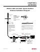
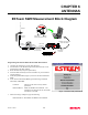
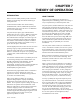
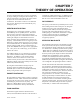
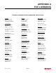
Table Of Contents

CHAPTER 6
ANTENNAS
Revised: 27 Mar 01
6-8
ESTeem SWR Measurement Block Diagram
Programming The ESTeem Model 192 For SWR Measurements
1.
Configure the hardware as per the above diagram.
2.
Turn Switch 2 on the RS-232 Setup Switch (located on the rear of
the ESTeem) to the OFF position.
3.
Reset the ESTeem (front panel push button).
4.
Install the ESTeem Utility on the PC hard drive as per instructions
with the software.
5.
From Utility Main Menu (Figure 1) select the Terminal Emulation
Mode.
6.
In the Terminal Emulation Mode type the following commands
followed by a RETURN.
FA Return This returns the unit to factory default
parameters.
RAD ON Return Enable the RADIO ON command. The
transmitter will alternate ON for 10 seconds
and OFF for 3 seconds.
7.
When the testing is completed, type the following:
RAD OFF Return This disables the RADIO ON command.
N Male
Connector
N Male
Connector
TNC Male
Connector
Antenna
2 Pin Molex
Connector
RS-232C Interface Cable
(EST P/N AA061)
UHF Male
Connector
SWR Meter
RG-8 Cable
(EST P/N AA230)
12 VDC Power Suppl
y
(EST P/N AA174)
S/N:T/E
TX
RX
PWR
IR
Port
Phone
Model 192S
Antenna
12 VDC
RESE T
ESTeem Model 192 Utility
Software Windows Version
Figure 1: ESTeem Utility Main Menu