
User's Manual

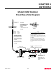
Table Of Contents

CHAPTER 6
ANTENNAS
Revised: 27 Mar 01
6-2
EST offers different types of antennas ranging from 1/4
wave to 5/8 wave in physical size. The user choice is
dependent on the application.
Communications in the VHF and UHF bands are
normally over
"Line of Sight (LOS)"
. Looking from the
antenna of one wireless modem you must be able to see
the antenna of the wireless modem you wish to
communicate with. If a large object obstructs the line of
sight view it is unlikely that satisfactory communications
will result. This means you must relocate the antennas or
use the REPEATER FEATURE and a second modem to
go over or around the object.
The Model 192C/F/M products are allowed by the FCC
to use high gain directional antennas.
It is noted that a 1/4 wave antenna that does not have
ground plane radials requires a ground plane to operate
at maximum efficiency. This can simply be a conducting
surface under the antenna that is a 1/4 wave length in
diameter. For the Model 192C this is approximately 6.5
inches. A conducting surface can be anything from the
roof top of an automobile to a file cabinet.
COAXIAL CABLES
To minimize signal loss, the overall length of the coaxial
cable should be as short as possible. To avoid corrosion
select coaxial cable manufacturers with tinned copper
braid, where possible. Listed below are representative
cable losses in db/100ft at the VHF and UHF frequencies:
Frequency (MHz) RG-58u RG-8 ½” Heliax
---------------------------------------------------------------------
150-174 - 5.2 - 2.3 - 0.845
402-420 -10.0 - 4.2 - 1.5
450-470 -10.8 - 4.4 - 1.5
In a severe noise environment it my be desirable to use a
double shield type of coax cable such as RG-214/U.
Note:
Pre-made coax cables can be purchased from
the factory. A -3 dB loss means you have lost
1/2 of your signal. A +3 dB gain means you
have doubled (x2) your signal.
Keep the antenna feedline as short as
possible to minimize losses.
Extreme care must be taken when attaching
coax connectors to the antenna feedlines.
If there is any error in making this
connection the output of the transmitter will
be greatly reduced.
WEATHER PROOFING COAX
CONNECTIONS
1. Coat the threads of the connectors with silicone
lubricant prior to assembly (See Note 1) and hand
tighten. Care should be taken not to get any
lubricant on the center conductor.
2. Wrap the connector assembly with a vapor barrier
patch for weather proofing (See Note 2), ensuring to
overlap onto the coax cable approximately 1 1/2
inches.
3. Apply a electrical coating (sealing agent) over the
vapor barrier patch for added protection (See Note
3).
Notes:
1. Dow Corning RTV-3140 or equivalent.
2. Suggested vendors:
VAPOR-WRAP
Decibel Products
3184 Quebec St.
Dallas, TX 75356
214-631-0310
VYNIL-MASTIC, P/N 2200
3-M Company
Customer Service
512-984-1800
3. SCOTCHKOTE, 3-M Company, or equivalent.
GROUNDING
All building mount antennas require attachment to a
good earth ground for optimum efficiency. Contact a
reputable local communications shop for procedures for
your area.