
User's Manual
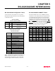

Table Of Contents

CHAPTER 5
RS-232C/422/485 INTERFACING
Revised: 27 Mar 01
5-3
MEMORY BUFFERS
The ESTeem has a 4000 byte buffer on the TRANSMIT
SIDE (outgoing data) and a 4000 byte buffer on the
RECEIVE SIDE (incoming data).
Transmit Buffer
The outgoing data buffer will hold two data blocks before
the ESTeem will enable its RS-232C hardware/software
flow control on data coming into the modem if the
network is busy. A data block in this example is a block
of data that is defined by the PACKLENGTH or
SENDPAC character which ever occurs first.
Therefore, if PACKLENGTH = 10 the modem will input
a maximum of 20 bytes before it enables its
hardware/software handshake line (two 10 byte packets).
In another example, if PACKLENGTH = 2000 but the
data block is terminated by the SENDPAC character
before the input buffer reaches the full 2000 bytes, the
buffer will still hold only two data blocks if the network
is busy.
In order to utilize the 2000 bytes storage for small data
packets (bar code readers, etc.), program the modem
using the following guidelines:
PACKLENGTH = 2000 SENDPAC = 255
TERMC = ON TERMT = 10
Note: Set the TERMT time greater than the pause
between data bursts.
By programming the above parameters the ESTeem will
buffer the incoming data packets and automatically
transmit the data when the 2000 byte buffer is filled or
the TERMT time limit is met. This will allow the
customer to use two blocks of 2000 or 4000 bytes before
the modem enables the respect hardware/software
control.
Receive Buffer
If the device that the receiving ESTeem is outputting data
to, enables its respective hardware or software control,
the modem will store 4000 bytes of data before flow
controlling off the transmitting ESTeem.
DATA TERMINAL READY (DTR)
A software switch, DTR_ENAB (ON/OFF) is provided in
the ESTeem for monitoring the status of a device
connected to pin 20 of the RS-232C connector. The
factory default setting is OFF. When this command is
enabled the ESTeem will monitor the DTR signal on pin
20. If the DTR line being supplied to the ESTeem, from
the user, is at a SPACE (high) condition then the
ESTeem is enabled. If the DTR line is at a MARK (low)
condition then the ESTeem is disabled.
This signal is normally used by the ESTeem modem as
an indication that connection is made to a device that is
on line and ready to transmit/receive data.
RS-422/485 CONFIGURATION
The ESTeem will support the requirements of the EIA
Standard RS-422/485. This is a four (4) wire interface
consisting of the TRANSMIT DATA (-), TRANSMIT
DATA (+), RECEIVE DATA (-), AND RECEIVE
DATA (+) or a two (2) wire interface using B (+) and A
(-). These signals are available at the 25 pin RS-232C
connector on the modem.
Pin Description
9 BTR (-) TRANSMIT DATA (-)
10 BTR (+) TRANSMIT DATA (+)
DCE 14 BRX (+) RECEIVE DATA (+)
(4-Wire) 16 BRX (-) RECEIVE DATA (-)
Pin Description
DCE 14 (+) HALF-DUPLEX B (+)
(2-Wire) 16 (-) HALF-DUPLEX A (-)
This interface is designed to provide unipolar differential
drive to twisted pair or parallel wire transmission lines.
Note: The ESTeem is configured at the factory for
RS-422 interfacing . RS-485 (either 4 or 2 wire
mode) requires internal jumper configuration.
Please contact EST Customer Support at 509-
735-9092 for instruction.
The ESTeem can be factory configured RS-485
interfacing prior to shipment. Call EST
Customer Support on 509-735-9092 for further
details.