
User's Manual
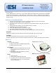

RF Switch Interface, v1.0 Installation Guide
www.elec-solutions.com © 2012 Electronic Solutions, Inc. Page 7 of 10
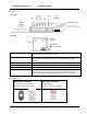
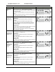
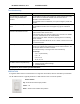
Mode
Description
DIP Switch setting
Group #4 sends commands to Net Group 4.
Net Groups 5, 6, 7, and 8
The Group #1 (Open or Close) button will send commands to
all motors that were assigned to Net Group 5.
Group #2 sends commands to Net Group 6.
Group #3 sends commands to Net Group 7.
Group #4 sends commands to Net Group 8.
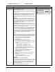
Net Groups 9, 10, 11, and 12
(follows the pattern described above).
Net Groups 13, 14, 15, and 16
(follows the pattern described above).
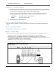
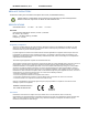
Step 5 — Install Battery
Install battery into the RF Switch Interface.
LED shows a startup blink sequence.
The green LED blinks for 60 seconds during Network Search mode, then turns off.
Result: RF Switch Interface enters Network Search mode (for 60 seconds), and does not find a network.
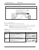
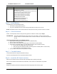
Step 6 — Join the Network
NOTE: If the RF Switch Interface was previously joined to an ESI RF network, skip to Step 7.
ASSUMPTION: An ESI RF network already exists, with one or more motors, and one or more SUITE
remotes. There is no active Network Invite on either the motors or SUITE remote (all LEDs
are off).
Join the RF Switch Interface to the ESI RF network.
1. Wake up the remote (press and release the UP or DOWN button).
2. Put the remote into Setup Mode.
3. Put the remote into Network Invite mode (press and release the STOP button).
4. Single press the Network button on the RF Switch Interface (starts Network Search).
Green LED starts blinking (RF Switch Interface).
Hub motor jogs once when RF Switch Interface joins the network (within a few seconds).
Green LED turns off (RF Switch Interface).
5. The RF Switch Interface has now joined the network.
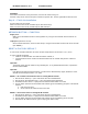
Step 7 — Test Wall Switch
Test shade movement using the wall switch button(s).
Test the functionality based on the Operational Mode chosen.
Step 8 — Install the RF Switch Interface
Mount the RF Switch Interface inside the wall, preferably inside a plastic junction box.
Place the RF Switch Interface behind the wall switch, and as close to the wall switch as possible.
WARNING:
Always use a plastic junction box. Metal junction boxes will greatly reduce the RF signal.