
User's Manual
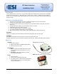

RF Switch Interface, v1.0 Installation Guide
www.elec-solutions.com © 2012 Electronic Solutions, Inc. Page 6 of 10
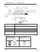
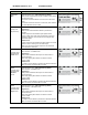
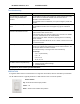
Mode
Description
DIP Switch setting
Set Net Group
Required Switch Type = n/a
Use the Set Net Group mode to send commands to a
different set of ESI RF motors. The default set is Net Groups
1, 2, 3, and 4.
If additional remotes and motors are joined into an ESI RF
network, the motors can be assigned to Net Groups 5, 6, 7, 8
or Net Groups 9, 10, 11, 12 or Net Groups 13, 14, 15, 16.
Use this operational mode to change to a different set of Net
Groups.
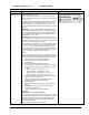
IMPORTANT: if at any point in the installation process, you
need to ―reset‖ the RF Switch Interface, for example, during
the ―Join the Network‖ step later on, you will need to Set the
Net Group again, because a ―reset‖ also defaults the Net
Groups back to 1, 2, 3, and 4.
ASSUMPTION: There is an active wire connection to the
Group # Open or Close button that you need to use to set the
correct Net Group. You may use a temporary jumper from the
Common to the Group # (Open or Close).
For example, if you intend to use only one wall switch, wired
to Group #1, but you want Group #1 to control Net Group 5
(or 9, or 13 — see Steps below for explanation), then you
need to run the jumper from Common to the Group #2 button
(for Net Group 5), or to the Group #3 button (for Net Group
9), or to the Group #4 button (for Net Group 13).
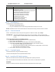
Steps
NOTE: if you change Net Groups, you must still choose one
of the previously listed Operational Mode DIP Switch settings
before continuing with the Installation steps (see 8. below).
1. Remove battery (if not already removed).
2. Set DIP Switches to Set Net Group mode.
3. Install battery.
4. After the version blink, the LED goes out.
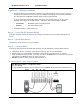
5. Press and release the Group # button (Open or Close)
that is associated with one of the following sets of Net
Groups:
Group #1 button = Net Group 1, 2, 3, 4
Group #2 button = Net Group 5, 6, 7, 8
Group #3 button = Net Group 9, 10, 11, 12
Group #4 button = Net Group 13, 14, 15, 16
6. The green LED blinks once each time that you press a
Group #1, #2, #3, or #4 button.
NOTE: each time you press a Group # button, it
overwrites the previous Net Group value.
7. Remove battery.
8. Set the DIP Switches to one of the other Operational
Modes.
9. Install battery. After the green LED blinks for 60
seconds, the LED turns off.
[skip to Step 6 below “Join the Network”]
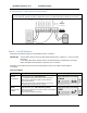
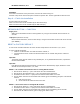
Scenarios
Net Groups 1, 2, 3, and 4 (the Default).
If you press a button (Open or Close) for Group #1 on the RF
Switch Interface, commands are sent to all motors that were
assigned to Net Group 1 during the ESI RF network setup.
The Group #2 button will send commands to all motors
assigned to Net Group 2.
Group #3 sends commands to Net Group 3.