
User's Manual
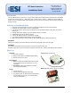

RF Switch Interface, v1.0 Installation Guide
www.elec-solutions.com © 2012 Electronic Solutions, Inc. Page 4 of 10
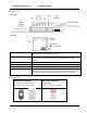
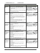
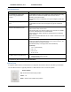
Wiring Diagram — SPDT Momentary switch (SPCO)
SPDT Momentary switch (SPCO) — Rocker switch with Center Off position
Up to four switches. Repeat the wiring configuration shown, for switches attached to Group #2, #3, and #4.
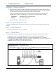
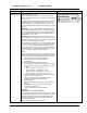
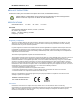
Step 4 — Set DIP Switches
Change the DIP Switch settings on the RF Switch Interface, if needed.
IMPORTANT: The RF Switch Interface reads the DIP Switch settings ONLY at power up — after you install
the battery.
If you change DIP Switch settings after the RF Switch Interface is powered up, the change
will not take place until the battery is removed, then re-installed.
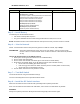
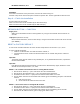
Determine the operational mode needed for the RF Switch Interface, then adjust the DIP Switches
accordingly.
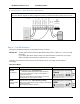
Operational Modes
Mode
Description
DIP Switch setting
Default
(as shipped)
Required Switch Type = SPST Momentary
(individual momentary buttons for Open and Close)
Motor moves to limit when an Open or Close button is
pressed and released.
Motor stops if both Open and Close buttons are pressed
simultaneously and motor was not at a limit.
SOBR
(stop on button
release)
Required Switch Type = SPDT Momentary (SPCO)
Motor moves toward limit as long as an Open or Close button
is pressed and held.
Motor stops when button is released.