
User's Manual
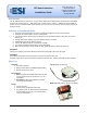

RF Switch Interface, v1.0 Installation Guide
www.elec-solutions.com © 2012 Electronic Solutions, Inc. Page 3 of 10
Installation — Starting Conditions
1. All ESI RF devices must be installed, networked, and configured (limits, scenes, and so on) prior to
adding the RF Switch Interface into the system. Examples of ESI RF devices commonly used would
be a SUITE remote and M40RF or M50RF motors used for window shades.
To set up an ESI RF network with remotes and motors, see the instructions on any one of the
following product pages on the ESI website — SUITE Arc, SUITE Step, M40RF, or M50RF.
Instructions: M40/50RF System Quick Setup Guide
Website: http://elec-solutions.com/
2. RF Switch Interface — NOT powered up.
Step 1 — Verify ESI RF Network Exists
Verify that an ESI RF network of remotes(s) and motor(s) is already set up and configured with limits and
scenes.
Step 2 — Install Wall Switch
Install the dry contact device, such as a wall switch.
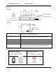
Step 3 — Connect Wires
Connect dry contact wires (20-26 AWG solid conductor) from the wall switch to the RF Switch Interface.
Insert wires. ―Push-in‖ connection. Push the bare end of the wire into the terminal block.
Release wires. Use a 2mm bladed screwdriver. Push screwdriver straight into slot, no levering.
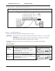
Hook up switches in Group # order. If you have one switch, you must hook it up to Group #1. If you have
two switches, you must use Group #1 and #2, and so on.
DO NOT connect the battery to the RF Switch Interface yet.
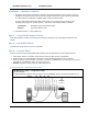
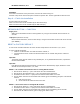
Wiring Diagram — SPST Momentary switch
SPST Momentary switch — Garage door switch
Up to four switches.
If a single Pushbutton switch is used for Group # control, it must be wired to the Close terminal for that #.