
User's Manual Part 3
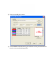
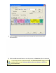

Thermocouple placement information entered in the sensor location matrix are
also displayed as the Sensor Locations in the Data Table.
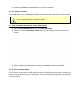
7) Enter sensor location dimensions. Sensor Locations can also be set by dragging
sensor location markers on the selected image. To move the markers, click the
Enlarge command button below the assembly image and the Set Sensor
Locations dialog box appears.
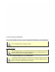
Specified X-dimensions may be altered when using the Align Profile Peaks
command to align the data run profile lines. Refer to topic
Software>Menus>Profile>Align Profile Peaks for more information.
X-dimensions are measured from the leading (right) edge or the first edge to
enter the process, and Y dimensions are from the top down.
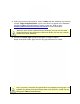
8) Select which sensor channels to display in the Data Table. Excluding a sensor
channel does not delete channel data and can be turned back on at any time. This
is helpful when data has been collected and it may not be beneficial to the data run
profile.