
User's Manual Part 3

• Thermocouple assembly which includes: 1 Thermocouple housing, 3 Hardware
Screws and 2 female pins (one marked with a green dot and one marked with a
white dot).
• A Thermocouple consisting of one yellow and one red wire. (Maximum T/C wire
size 24 gauge).
• Thermocouple crimping tool
• Phillips (Crosshead) Screwdriver
Construct a thermocouple as follows:
1) Disassemble the Thermocouple housing by unscrewing the 3 Hardware screws.
2) Separate the wires on the stripped lead end (opposite junction end) about ¾”.
3) Prep the Red (-) T/C wire stripping the wire casing about 0.10” and curling the bare
wire into a U-shape. Place it into the T/C pin with the green dot and crimp with the
T/C crimping tool. Make sure that the wire covering is clear through the first set of
shoulders and crimped by them. Also, be sure that only wire is crimped by the
second shoulders.
4) Repeat Step 3 for the Yellow (+) wire by placing it into the T/C pin with the white
dot.
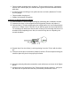
5) Place the female pins in the bottom (smaller) half of the Thermocouple housing. Be
careful to place the pins in the proper pin location.
6) Wrap the red and yellow wires around the strain relief posts as shown in the Figure
above.
7) Carefully place the two halves of the Thermocouple housing together. Verify that
the wires are not pinched and that the pin and wire positions are correct.