Contents 1. Introduction .............................................................................................................................................. 4 1.1. Copyright ............................................................................................................................................ 4 1.2. Declaration of Conformity ................................................................................................................. 6 1.3.
5.2. Installation & Authorization............................................................................................................. 81 5.2.1. Windows XP .............................................................................................................................. 83 5.2.2. Windows Vista .......................................................................................................................... 92 5.2.3. Windows 7 ......................................................
7. Service and Troubleshooting ................................................................................................................ 480 7.1. General Service Information .......................................................................................................... 480 7.2. SuperM.O.L.E.® Gold ...................................................................................................................... 480 7.2.1. Communications Problems .........................................
1. Introduction 1.1. Copyright ECD World Headquarters Electronic Controls Design, Inc. 4287B S.E. International Way Milwaukie, Oregon 97222-8825 U.S.A. Telephone: +(1) 800.323.4548 +(1) 503.659.6100 FAX: +(1) 503.659.4422 Email: ecd@ecd.com Internet: http://www.ecd.com Asia/China ECD Asia/Pacific Covent Garden Post Office P.O. Box 093, Singapore 911634 Telephone: +(65) 9.692.6822 FAX: +(65) 6.241.9890 Email: ecd.asia@ecd.com Europe ECD 4287B S.E. International Way Milwaukie, Oregon 97222-8825 U.S.A.
©2007-2011 ECD. All Rights Reserved. Printed in USA. US Products of ECD are covered by foreign and US Patents and Patents Pending. Information in this publication supersedes all previously published information. This Publication may not be translated and/or reproduced or stored in data retrieval system, or transmitted in any form or by any means without the express written permission of ECD. Specification and price change privileges reserved. The trapezoidal ECD logo®, MEGAM.O.L.E.®, V-M.O.L.E.®, SuperM.O.
1.2. Declaration of Conformity Electronic Controls Design, Inc. 4287-B S.E. International Way Milwaukie, Oregon U.S.A. 97222-8825 (503) 659-6100 / (800) 323-4548 FAX: (503) 659-4422 Declaration of Conformity Product: "Xpert Ready" SuperM.O.L.E.® Gold W/PP Part number: E40-2875-40 "Xpert Ready" SuperM.O.L.E.
Declaration of Conformity Product: SuperM.O.L.E.® Gold 2 Thermal Profiler Part number: E51-0386-40 The above product is in conformity with the following standards or other normative documents: • Electro Magnetic Compatibility Standard for Radio Equipment and Services EN 301 489-01 V1.8.1:2008 • Harmonized Standard for Data Transmission Equipment Operating in the 2.4 GHz Band EN 300 328 V1.7.1:2006 • Electro Magnetic Compatibility Standard for Radio Equipment and Services EN 301 489-17 V2.1.
1.3. How to use this Users Help Guide This Users Help System explains how to use ECD Thermal Profiling instruments and software. This Users Help System is written for users of varied experience. If a section covers information you already know, feel free to skip to the next section. • You do not need to be a computer expert to use this Users Help System or the software. • The Users Help System assumes you are familiar with Microsoft® Windows® Operating Systems.
1.4. Terms Used In 1986 ECD introduced our original Thermal Profiling instrument called the M.O.L.E.® (Multichannel Occurrent Logger Evaluator). Over the years ECD has produced several models of the M.O.L.E.® for use in a wide variety of applications. In this Users Help System, we may refer to all of our Thermal Profiling instruments as the M.O.L.E.® Profiler. The M.O.L.E.® Profiler is a registered trademark of ECD.
1.5. Fonts Used This manual uses a specific font to indicate terms or words that can be found directly on the display of the computer. For example: On the File menu, click Preferences to configure the software global settings. This font indicates the words File and Preferences are actually found on the computer display.
2. Safety 2.1. Operators Safety Information The safety information in this section is for the benefit of operating personnel. Warnings and Cautions will also be found throughout the manual where they apply. Hardware changes or modifications to the M.O.L.E. Profiler or components are not expressly approved by ECD and could void the warranty. The warranty will not cover damage caused by neglect or abuse of any ECD products.
For protection of the M.O.L.E. Profiler and components, observe the following: • NEVER permit the M.O.L.E. Profiler or the battery to exceed the maximum specified internal temperature as permanent damage may result. (Refer to Appendix A: Specifications). • NEVER expose the M.O.L.E. Profiler or battery to temperatures below the specified minimum for extended time periods. This may damage the rechargeable battery. • NEVER connect the M.O.L.E.
2.2. Battery Warnings Warnings: • Charge “Rechargeable” Power Pack batteries using only the ECD approved charger. • Do not attempt to recharge the SuperM.O.L.E.® Gold Profiler Calendar/Clock battery, disassemble, expose to temperature above 100°C (212°F) or dispose of in fire. • Always dispose of used batteries promptly and properly. • Keep all batteries away from children. • The batteries may explode if mistreated. • The batteries contain electrolytes. Replace the M.O.L.E.
2.3. Equipment Maintenance Maintain your equipment to prevent future problems and unwanted costs. Keep your M.O.L.E. Profiler at peak performance by taking care of the system components and keeping it calibrated. Typical maintenance should include the following: • Wipe the exterior of the instrument enclosure or components with a cloth dampened with water or IPA alcohol. IPA alcohol is the only type of solvent that is acceptable to clean Thermal Profiling instruments or any of the system components.
2.4. Product Symbols The following symbols may be present on the M.O.L.E.
CAUTION: Whenever this internationally recognized symbol is used on the product, additional information concerning that particular feature or function appears in the manual. European Conformity FCC Federal Communications Commission (FCC) Power transformer is protected throughout by double or reinforced insulation. Indoor use only. For electric-shock protection, always operate the battery charger in a protected, indoor location.
3. Equipment 3.1. SuperM.O.L.E.® Gold The SuperM.O.L.E.® Gold Profiler is compact and durable. One end has input connectors for attaching up to (6) sensors and the other end is the removable Power Pack. It also has a four-pin Data port, Start/Stop button, and an Activity LED. Features/Functions: • Thermocouple/Inputs:This is where Type “K” or “S” Thermocouples and the optional Relative Humidity sensors are connected. • Start/Stop button: Allows the user to start and stop data collection.
3.1.1. Power Pack Because the SuperM.O.L.E.® Gold Profiler is powered by a removable Power Pack, it is important to make sure it is charged and operating properly. When connected to a computer, the software displays the voltage of the Power Pack on the Status bar. Refer to topic Software>Features>Status Bar for more information. When the Power Pack needs to be re-charged use the charger supplied with the kit and the instructions in topic Basics>Setup>Charging the Power Pack.
3.1.2. Calendar/Clock Battery The SuperM.O.L.E.® Gold Profiler has another battery that powers an internal calendar and clock. This battery is not rechargeable and has no status indicator. The expected battery life is about 2-3 years. If the calendar and clock does not seem to operate (it resets itself), the battery may be discharged. For information on replacing the calendar/clock battery refer to topic Service>Changing the Calendar/Clock Battery.
3.1.3. Sensors Up to six sensors can be attached to the SuperM.O.L.E.® Gold profiler per experiment. A set of six 0.010” K-Type Color-Indexed thermocouple sensors are included in the Kit. Plug the sensor connector into the desired SuperM.O.L.E.® Gold profiler channel. The software helps keep a record of the SuperM.O.L.E.® Gold profiler channel number associated with the location and the type of sensor.
3.1.4. Computer Interface Cable A Cable is included in the hardware package that connects the SuperM.O.L.E.® Gold Profiler to a computer serial port. The SuperM.O.L.E.® Gold Profiler requires a four-pin connector and a nine-pin for the computer serial port. If your computer does not have an available Serial port, the Kit includes a USB adaptor that connects the SuperM.O.L.E.® Gold to the computer via a USB (Universal Serial Bus) port.
3.1.5. Uni-Barrier & Yellow Jacket The Uni-Barrier with Yellow Jacket is the standard barrier in all our Lead-Free profiling kits, including the wireless RF kit. A thermal barrier is the protection the SuperM.O.L.E.® Gold needs to ensure longevity through harsh environments. With piano-hinged stainless steel construction, sheathed in cool-to the touch high-temperature fabric this thermal barrier is ideal for lead-free processes. This barrier is rated to protect the SuperM.O.L.E.® Gold for 7 minutes at 200C.
3.2. SuperM.O.L.E.® Gold 2 The SuperM.O.L.E.® Gold 2 continues the legacy of the original SuperM.O.L.E.® Gold. With all the power of a MEGAM.O.L.E.® 20. It retains the same form factor, thermocouple connector type, and channel count (6) in addition to individual channel LEDs. • RED indicates channel is “active”, as configured in the software. • GREEN indicates that thermocouple is plugged in and a complete circuit.
Button: ON/OFF Record OK • Action: Turns Profiler "ON/OFF". Starts/Stops Profiler recording data. Invokes "OK" process where the last recorded profile is compared to pre-configured criteria resulting in a "Pass" or "Fail" mode. Activity Indicators: These are LED's that indicate what state the SuperM.O.L.E.® Gold 2 Profiler is in. Refer to the illustration and table below.
3.2.1. Sensors Up to (6) sensors can be attached to the SuperM.O.L.E.® Gold 2 profiler per experiment. A set of six 0.010” K-Type Color-Indexed thermocouple sensors are included in the Kit. Plug the sensor connector into the desired SuperM.O.L.E.® Gold 2 Profiler channel. The software helps keep a record of the SuperM.O.L.E.® Gold 2 Profiler channel number associated with the location and the type of sensor.
3.2.2. USB Computer Interface Cable A USB cable is included in the hardware package. This cable connects the SuperM.O.L.E.® Gold 2 Profiler to a computer USB port and optional charger.
3.2.3. Barrier & Yellow Jacket The Uni-Barrier with Yellow Jacket is the standard barrier in all our Lead-Free profiling kits, including the wireless RF kit. A thermal barrier is the protection the SuperM.O.L.E.® Gold 2 needs to ensure longevity through harsh environments. With piano-hinged stainless steel construction, sheathed in cool-to the touch high-temperature fabric this thermal barrier is ideal for lead-free processes. This barrier is rated to protect the SuperM.O.L.E.® Gold 2 for 7 minutes at 200C.
3.2.4. Wireless RF Option The Wireless RF Option for the SuperM.O.L.E.® Gold 2 Profiler produces real time profiles for immediate data collection. The Transmitter is an built-in component that when used with the antenna sends data to the RF transceiver which connects to a USB port on the computer. Wireless RF Transceiver: This is not a memory “thumb drive” but a full featured RF transmitter and receiver (Transceiver) used to create the wireless RF link to the SuperM.O.L.E.® Gold 2.
4. Basics 4.1. Setup The Setup topic offers a brief description of the system hardware configuration. 4.1.1. Charging the Power Pack Because the M.O.L.E. Profiler is powered by a rechargeable Power Pack, it is important that it is charged and operating properly prior to performing every experiment. When using a MEGAM.O.L.E.® or SuperM.O.L.E.® Gold a spare removable Power Pack may be ordered so one is charging while the other one is being used.
4.1.1.1. SuperM.O.L.E.® Gold To charge the Power Pack: 1) Remove the Power Pack by separating from the unit. 2) Plug the transformer end of the charger into a (60Hz 120VAC, in North America) or (230VAC) wall outlet and the connector end into the Power Pack. A completely discharged Power Pack takes about 14 hours to be fully charged. 3) When the charging cycle is complete, connect the Power Pack to the M.O.L.E. Profiler.
4.1.1.2. SuperM.O.L.E.® Gold 2 To charge the internal Power Pack: 1) Insert the USB computer interface cable into a computer USB port and the other end into the Data/Charging Port. A completely discharged Power Pack takes about 8 hours to be fully charged. For quick charges, it can be charged for 15 minutes allowing one 10 minute data run to be performed. The Power Pack can be charged continuously whenever the M.O.L.E. Profiler is not being used, however, if the M.O.L.E.
4.1.2. Communications Setup Prior to operation the M.O.L.E. Profiler must be configured to properly communicate with the M.O.L.E.® MAP Software. The M.O.L.E.® MAP software must be installed prior to communications setup. (Refer to Software Installation for more information). 4.1.2.1. SuperM.O.L.E.® Gold To connect the M.O.L.E. Profiler: The M.O.L.E.® MAP software must be installed prior to communications setup. (Refer to Software Installation for more information).
3) Start the software program by either double-clicking the M.O.L.E.® MAP software icon or selecting it from the ECD program sub-menu. 4) On the M.O.L.E. menu, click the Select Instrument command. 5) Select the desired instrument from the dialog box. If there are none displayed, click the Scan for Instruments command button to detect all available instruments. If the software does not detect a M.O.L.E.
4.1.2.2. SuperM.O.L.E.® Gold 2 To connect the M.O.L.E. Profiler: The M.O.L.E.® MAP software must be installed prior to communications setup. (Refer to Software Installation for more information). 1) Insert the USB computer interface cable into a computer USB port and the other end into the Data/Charging Port. The first time a M.O.L.E. Profiler is connected to a computer two drivers will be installed. One is a device driver for the M.O.L.E. Profiler and the other is for USB communication.
2) During installation of the device driver, when prompted to select the location of the device driver, select "Install the software automatically". Follow the remaining wizard instructions closely. 3) During installation of the USB driver a message box appears, select the Continue Anyway command button and the driver will be successfully installed.
4) After M.O.L.E. Profiler is connected to a computer, the software must be configured so they can communicate. Start the software program by either double-clicking the M.O.L.E.® MAP software icon or selecting it from the ECD program sub-menu. 5) On the M.O.L.E. menu, click the Select Instrument command. 6) Select the desired instrument from the dialog box. If there are none displayed, click the Scan for Instruments command button to detect all available instruments. If the software does not detect a M.O.
4.1.2.2.1. Wireless RF Option Setup To connect the wireless RF option: Prior to wireless RF communication, the M.O.L.E. Profiler must first be connected to a computer through the USB port. This allows the software to register the serial number of the M.O.L.E. Profiler. Registering the serial number ensures that other M.O.L.E. RF transmissions in close proximity to each other will not interfere preventing others from controlling your M.O.L.E. Profiler without your consent.
The Transceiver can either be connected directly to a computer USB port or a USB extension cable. Using an USB extension cable can be a simple way to get the Transceiver to a better reception area without moving the PC. No matter which method is used, keep wires and other metal objects away from the Transceiver. Good Poor 2) After the Transceiver is connected to a computer, it needs to be detected by the software to properly communicate. 3) Start the software program by either double-clicking the M.O.L.
4) On the M.O.L.E. menu, click the Read Instrument command. When the software detects the Wireless RF Transceiver for the first time, the user will be prompted to enter the 5 digit Unlock Key located on the product ID label. 5) Enter the Unlock Key in the field and select the OK command button. 6) If the unlock key is successfully entered, the software informs the user with a message box and the Blue RF indicator on the M.O.L.E. Profiler flashes.
7)Select the OK command button to continue. If the software does not detect a M.O.L.E. Profiler, using the communication cable connect it to the computer and click the Scan for Instruments command button to search again. M.O.L.E.® MAP software allows multiple instruments to be connected to a computer at one time. Selecting the Scan for Instruments command button will detect all instruments and display them in the dialog box.
9) Click the Finish command button to continue receiving RF data, or Cancel to quit the command. The system is now ready to start Wireless RF communication. Refer to topic: Menu and Tools Commands>Wizards Menu>Download Data>Wireless RF Communications to start the real-time wireless data collection.
Wireless RF communication tips (MEGAM.O.L.E.® & SuperM.O.L.E.® Gold 2): RF signals come and go as either the M.O.L.E. Profiler moves through the oven or the Transceiver is moved around like FM radio static as you drive in your car. Moving a few inches in any direction can turn a low signal strength to high signal strength. This gets worse as the Transceiver gets further from the M.O.L.E. Profiler, to a point where no position works.
4.2. Operation - Fresh Start This section guides the user through a typical collection process. Portions of this section require referral to some software sections of the Users Help System for additional information. The M.O.L.E.® MAP software is designed to be used with the ECD MEGAM.O.L.E.®, V-M.O.L.E.®, SuperM.O.L.E.® Gold, SuperM.O.L.E.® Gold 2 and PTP® VP-8 Thermal Profilers. Images used in software sections of this Users Help System typically refer to the SuperM.O.L.E.® Gold 2. The M.O.L.E.
4) On the File menu, click New/Start. A message box appears with the five workflow wizard options. 5) On the Start dialog box, click the Fresh Start command button and the workflow wizard appears. When navigating through the wizard, the step list on the left uses a color key to inform the user of the current step, steps that have been completed and remaining steps. Current Completed Remaining 6) Select the desired instrument from the dialog box to make active.
7) Click the Next command button. 8) Select a machine from the Machine drop down list. If the desired machine does not appear in the list click the New command button to create a new machine. Refer to topic Software>Menus>Machine>Create new Machine for more information.
9) Set the machine recipe settings such as Conveyor Speed, Zone Temperatures and Temperature units. The software includes features to save and load machine recipe setting files. These files are helpful so the user can quickly recall machine information and ensure it is always the same.
10) Click the Next command button. If no value is specified for the conveyor speed or the default machine temperature values, the software will remind the user to set them. 11) Enter the assembly information such as part number, board size, sensor locations and a product image. When using a SuperM.O.L.E.® Gold Profiler, if fewer than six sensors used, it is important that the unused channels are turned OFF or shorting plug(s) are used for each unused channel. Refer to topic Service>SuperM.O.L.E.
If a product image has been selected, clicking the Enlarge command button displays the Set Sensor Locations dialog box where the user can specify the locations of each sensor. To move sensor locations, drag the sensor markers to the approximate location where the sensors are attached.
12) When finished, click the OK command button to accept or Cancel to return without making any changes. 13) Click the Next command button. 14) Attach sensors to a test assembly. When soldering a T/C sensor to a component with high temperature solder, use Kester SN10 (or equivalent) for 183°C eutetic solder or Kester SN5 (or equivalent) for lead free soldering. 15) Unwind the sensor leads and attach the connectors to the M.O.L.E. Profiler.
16) Select your process specification. Select a Paste from the database or previously created Target 10 Specification. If your Paste does not appear in the database list click the New command button to create a new one. Refer to topic Software>Menus>Process>Create new Paste for more information. 17) Then choose the Profile Type (Ramp-Soak-Spike or Ramp-to-Spike). Ramp-Soak-Spike profile types are the only type allowed to be edited.
Once a paste is selected the specifications are displayed on the graph. The software also allows paste specification data to be viewed in a table view by clicking the Table command button.
18) Click the Next command button 19) Set Recording Parameters such as the instrument name, recording interval, start parameters and stop parameters. This step is where the user can also turn a sensor channel ON or OFF, set the sensor location description and sensor type. Refer to topic Software>Menus>M.O.L.E.>Set Recording Parameters for detailed information for each setting.
20) Click the Next command button. If the currently selected M.O.L.E. Profiler is a SuperM.O.L.E.® Gold, sending recording parameters will erase the data currently stored in the M.O.L.E. Profiler. The software will warn the user with a message box. 21) Verify the instrument status. This dialog box displays the health of the M.O.L.E. Profiler such as Power Pack charge, internal temperature, thermocouple temperatures. If everything is OK, the dialog box displays a GREEN sign.
22) Click the Next command button. 23) Review the oven settings and click the Next command button to continue.
Step 2: Perform Data Run 1) Place the M.O.L.E. Profiler in the appropriate thermal barrier making sure the Thermocouple and/or Sensor wires are not damaged. Never permit the M.O.L.E. Profiler to exceed the absolute maximum warranteed internal temperature, as permanent damage may result. The warranty will not cover damage caused by exceeding the maximum specified internal temperature. 2) After the oven stabilizes, turn the M.O.L.E. Profiler ON and press the record button. When using a SuperM.O.L.E.
It is highly recommended that protective gloves are used when retrieving the thermal barrier from the oven and when opening the thermal barrier. 4) As the test assembly and M.O.L.E. Profiler emerge from the machine, carry the test assembly with sensors attached and the M.O.L.E. Profiler in the Thermal barrier to a table or flat surface. If a sensor is removed before the M.O.L.E. Profiler has stopped collecting data, the data for that channel might become distorted.
• When using a SuperM.O.L.E.® Gold Thermal Profiler, prior to reading the data run, the software prompts the user to select the sensor type for the active channels. When finished select the OK command button to proceed.
2) When the data run has been downloaded, the software suggests a default file name or prompt the user to specify a new file name (*.XMG). When saving a data run (*.XMG) to a different file directory other than the current Working directory, the software automatically sets the new file directory as the current Working Directory. This process does not delete any data run files in the previously set Working directory and can be quickly accessed using the Recent Working Directory command on the File menu.
I 3) When finished, click the Save command button. 4) The software then prompts the user if they want to enter Prediction mode. Entering prediction mode enables the user to change a zone temperature values or the conveyor speed and predict the outcome of that change on the data run profile. Refer to topic Software>Menus>Tools>Prediction for more information. 5) Click the Predict command button to enter Prediction mode or Done to complete the workflow wizard .
4.3. Operation - Verify This section guides the user through a typical verification process. Portions of this section require referral to some software sections of the Users Help System for additional information. The M.O.L.E.® MAP software is designed to be used with the ECD MEGAM.O.L.E.®, V-M.O.L.E.®, SuperM.O.L.E.® Gold, SuperM.O.L.E.® Gold 2 and PTP® VP-8 Thermal Profilers. Images used in software sections of this Users Help System typically refer to the SuperM.O.L.E.® Gold 2.
4) Click the Next command button. 5) Select a data run. This is the data run that is known to be good and the user wishes to confirm the process is reproducing faithfully using the verify process. If the selected data run was created using a recording interval other than 1.0 second, the Slope calculation will not be included in the Target10 Specification.
This list displays the data runs from the currently open working directory. 6) Click the Next command button. 7) Map the desired channels from selected data run to channels of the M.O.L.E. Profiler. These typically are the most important channels that best represent the process being verified.
The software displays all the channels in the selected thermal profile. The thermal profile selected in the sample was taken from a 20-channel MEGAM.O.L.E.® thermal profile. 8) Click the Next command button. 9) Once the channels are mapped, review the results of the Target 10 specification. The user can then decide if they wish to send these to the M.O.L.E. Profiler or make final modifications to the Slope, Soak, Time Above and/or Peak parameter.
10) If the user decides to make modifications, click the Modify Target10 command button and the the Target 10-OK tab is displayed. Make the desired modifications to the Slope, Soak, Time Above and/or Peak parameter specifications. If any of the parameter specifications are changed the OK button will inform the user by displaying (OKModified).
11) Click the OK command button to accept the modified specifications or Cancel to discard them and return to the workflow wizard.
12) If the user either decides to send the Target10 to the M.O.L.E. Profiler or complete the wizard by clicking the Finish command button, the software prompts the user to save the Target 10 file (*.T10). Only the MEGAM.O.L.E.®, V-M.O.L.E.® and SuperM.O.L.E.® Gold 2 can have the Target 10 sent to them. When using the SuperM.O.L.E.® Gold the Target 10 will only be able to be saved as a file.
13) When finished naming the file, click the Save command button to complete the workflow wizard.
Step 2: Verify Process This is available in both Engineer & Verify Modes. 1) Connect the M.O.L.E. Profiler to the computer. Refer to Basics>Setup>Communications Setup for more information. 2) On the File menu, click New. The Start dialog box appears with the five workflow wizard options. 3) On the Start dialog box, click the Verify Process command button and the workflow wizard appears.
5) Click the Next command button. 6) Select a Target 10 file from the list to verify. When placing the mouse cursor over a file on the list, a thumbnail image appears to help properly identify the assembly associated with it.
When selecting a Target 10 file to verify, the software displays files located in the \ECD\MegaMoleMAP\Target10Spec\ directory that are associated with the currently selected instrument. 7) Click the Next command button. 8) Verify the instrument status. This dialog box displays the health of the M.O.L.E. Profiler such as battery charge, internal temperature, thermocouple temperatures. If everything is OK, the dialog box displays a GREEN sign.
9) Click the Next command button. 10) Review the machine settings and click the Next command button to continue.
11) Attach sensors to a test assembly. Make sure to connect them to the same locations that were used when creating the verification specification file. If the same test assembly is being used that was used to create the verification specification file, no thermocouple attachment will be required. When soldering a T/C sensor to a component with high temperature solder, use Kester SN10 (or equivalent) for 183°C eutetic solder or Kester SN5 (or equivalent) for lead free soldering.
12) Unwind the thermocouple sensor leads and attach the connectors to the M.O.L.E. Profiler. Never permit the M.O.L.E. Profiler to exceed the absolute maximum warranteed internal temperature, as permanent damage may result. The warranty will not cover damage caused by exceeding the maximum specified internal temperature.
13) After the oven stabilizes, turn the M.O.L.E. Profiler on and press the record button. The record button will need to be pressed even if the M.O.L.E. Profiler is configured to start if the start parameters Trigger Temperature or Points Delay are configured. 14) Pass the thermally protected M.O.L.E. Profiler and test assembly through the machine. It is highly recommended that protective gloves are used when retrieving the thermal barrier from the oven and when opening the thermal barrier.
analyzes the most recent data run to verify the Target 10 Specifications applied to the previously selected data run. Only the MEGAM.O.L.E.®, V-M.O.L.E.® and SuperM.O.L.E.® Gold 2 are equipped with the OK button. When using the SuperM.O.L.E.® Gold please skip the previous step. 20) Connect the M.O.L.E. Profiler to the computer and click the Next command button. 21) Select the desired data run and then click the Next command button to read the data run from the M.O.L.E. Profiler.
22) When the data run has been downloaded, the software prompts the user to save the verification data run file (*.XMG). When saving a data run (*.XMG) to a different file directory other than the current Working directory, the software automatically sets the new file directory as the current Working Directory. This process does not delete any data run files in the previously set Working directory and can be quickly accessed using the Recent Working Directory command on the File menu.
23) When finished, click the Save command button. 24) Click the Next command button to show the Target 10-OK results.
25) Analyze the data by selecting the Target10-OK tab on the Profile Tab.
5. Software 5.1. Computer Hardware Requirements The following computer hardware requirements are necessary for the software to properly perform: Hardware: • 300mhz processor or equivalent • 128 megabytes of RAM (minimum) • 50 megabytes of free disk space • CD ROM • USB Port (MEGAM.O.L.E.®, V-M.O.L.E.®, SuperM.O.L.E.® Gold 2 & PTP® VP-8) • Serial Port (SuperM.O.L.E.
Operating System: • Windows 7 • Windows Vista • Windows XP • Windows 2000 Languages: M.O.L.E.® MAP software is available in the following languages for the above operating systems: • English • Chinese Simplified • Chinese Traditional • Italian 5.2. Installation & Authorization Prior to Installation: • The user must have administrator permissions for the computer to install M.O.L.E.® MAP • Verify that no M.O.L.E.® Profilers are attached to your system.
Manual Install: 1) Insert the CD in the drive. 2) Select Run from the Start menu. 3) Select the Browse command button and navigate to the software CD. Double-click the installation (.EXE) file. 4) Select the OK command button to start the installation. Closely follow the installation instructions for your operating system.
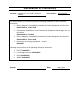
5.2.1. Windows XP Prior to Installation: • The user must have administrator permissions for the computer to install M.O.L.E.® MAP • Verify that no M.O.L.E.® Profilers are attached to your system. (DO NOT connect your M installation is complete.) • The first time you run the M.O.L.E.® MAP software on Windows Vista or 7, it MUST be ru Step 1: Installation Instructions: 1) Select the Install Software button on the Autorun dialog to prepare the software for installation.
2) Select the Next command button to continue the installation process.
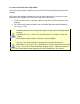
3) Review the Licence Agreement. 4) Select the Accept option and the Next command button to continue. 5) Select your Application and the Next command button to continue.
6) Select the Install command button to install the program. 7) Select the Install command button to install the USB drivers so the software can communicate with the M.O.L.E.® Profiler.
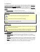
8) Once the USB drivers are installed the a message box prompts the user to decide if they would like to restart the computer now. If Yes is selected, the software installation will continue and the computer will be restarted. If No is selected, the user will need to restart the computer before the software can communicate with the M.O.L.E.® Profiler. 9) To complete the installation, select the Finish command button.
Install complete. An Users Help System icon appears on desktop. Step 2: Starting the Software: Prior to starting, click the README icon from the M.O.L.E.® MAP program sub-menu to read the latest release notes. After the software is installed, start the software program by double-clicking the M.O.L.E.® MAP icon from the desktop. Once the software installation and is running correctly, it is important to start the software and configure the software to communicate with the M.O.L.E. Profiler.
A Software Unlock Key can be obtained via the web or using the contact information supplied on the dialog box, contact ECD. To Web Authorize: 1) On the File menu, click Preferences, and then click the Misc tab. 2) In the Authorization section, click the Authorize command button and the Authorization dialog box appears. 3) Enter the required information on the M.O.L.E.® MAP Software Authorization form.
4) When finished select the Submit button. A confirmation screen appears indicating that the Software Unlock Key has been sent to the email address provided in the form.
5) Enter the 16-digit Software Unlock Key and then the Start MAP command button to complete the software Authorization. If the software is activated at a later time, YOU MUST repeat running it as an administrator as described in Step 2: Starting the Software as the program will not remember it has been activated.
5.2.2. Windows Vista Prior to Installation: • The user must have administrator permissions for the computer to install M.O.L.E.® MAP • Verify that no M.O.L.E.® Profilers are attached to your system. (DO NOT connect your M installation is complete.) • The first time you run the M.O.L.E.® MAP software on Windows Vista or 7, it MUST be ru Step 1: Installation Instructions: 1) Select the Install Software button on the Autorun dialog to prepare the software for installation.
3) Review the Licence Agreement. 4) Select the Accept option and the Next command button to continue. 5) Select your Application and the Next command button to continue.
6) Select the Install command button to install the program. 7) Select the Allow button to continue.
8) Select the Install command button to install the USB drivers so the software can communicate with the M.O.L.E.® Profiler. 9) To complete the installation, select the Finish command button.
Install complete. A Users Help System icon appears on desktop. Step 2: Starting the Software: The first time you run the M.O.L.E.® MAP software on Windows Vista or 7, it MUST be run as an “Administrator” 1) Right-click the Windows start icon (lower left corner) and select Explore to Open Windows Explorer from the menu.
2) Navigate to the M.O.L.E.® MAP installation directory. This is typically is C:\ECD\MegamoleMAP. 3) Right-click the MM_MAP218 icon and select Run as administrator from the menu.
4) Select Allow to allow the operating system to run the software as an administrator. Once the software installation and is running correctly, it is important to start the software and configure the software to communicate with the M.O.L.E. Profiler. Refer to topic Basics>Setup for more information.
The software is a fully functional 30-day trial version that can be authorized at any time. Once the trial period is over, the user cannot access the software until it is authorized. A Software Unlock Key can be obtained via the web or using the contact information supplied on the dialog box, contact ECD. To Web Authorize: 1) On the File menu, click Preferences, and then click the Misc tab. 2) In the Authorization section, click the Authorize command button and the Authorization dialog box appears.
4) When finished select the Submit button. A confirmation screen appears indicating that the Software Unlock Key has been sent to the email address provided in the form.
5) Enter the 16-digit Software Unlock Key and then the Start MAP command button to complete the software Authorization. If the software is activated at a later time, YOU MUST repeat running it as an administrator as described in Step 2: Starting the Software as the program will not remember it has been activated.
5.2.3. Windows 7 Prior to Installation: • The user must have administrator permissions for the computer to install M.O.L.E.® MAP • Verify that no M.O.L.E.® Profilers are attached to your system. (DO NOT connect your M installation is complete.) • The first time you run the M.O.L.E.® MAP software on Windows Vista or 7, it MUST be ru Step 1: Installation Instructions: 1) Select the Install Software button on the Autorun dialog to prepare the software for installation.
3) Review the Licence Agreement. 4) Select the Accept option and the Next command button to continue. 5) Select your Application and the Next command button to continue.
6) Select the Install command button to install the program. 7) Select the Yes command button to continue the installation.
8) Select the Install command button to install the USB drivers so the software can communicate with the M.O.L.E.® Profiler. 9) To complete the installation, select the Finish command button.
Install complete. A Users Help System icon appears on desktop. Step 2: Starting the Software: The first time you run the M.O.L.E.® MAP software on Windows Vista or 7, it MUST be run as an “Administrator” 1) Right-click the Windows start icon (lower left corner) and select Explore to Open Windows Explorer from the menu.
2) Navigate to the M.O.L.E.® MAP installation directory. This is typically is C:\ECD\MegamoleMAP. 3) Right-click the MM_MAP218 icon and select Run as administrator from the menu.
Once the software installation and is running correctly, it is important to start the software and configure the software to communicate with the M.O.L.E. Profiler. Refer to topic Basics>Setup for more information. Step 3: Software Authorization: The software is a fully functional 30-day trial version that can be authorized at any time. Once the trial period is over, the user cannot access the software until it is authorized.
3) Enter the required information on the M.O.L.E.® MAP Software Authorization form. 4) When finished select the Submit button. A confirmation screen appears indicating that the Software Unlock Key has been sent to the email address provided in the form.
5) Enter the 16-digit Software Unlock Key and then the Start MAP command button to complete the software Authorization.
5.3. Features This section presents an overview of the software window. When the software is started, it automatically defaults to the previously open working directory. Refer to topic Software>Menus>File>Open Working Directory for more information. After installation, the software is started a with the a sample working directory with files will be selected for users to familiarize themselves with the program.
Split Bar: This bar slides the Horizontal Scroll bar to the left or right so all or part of the page tabs can be viewed. Status Bar: This bar on the bottom of the display, shows the status of the M.O.L.E. Profiler Power Pack battery, Internal operating temperature, connected COM port, available Help information, mouse pointer X-Y position, current date and time. Scroll Bars: These bars scroll the display horizontally and vertically. AutoPlay: This feature offers quick access to the M.O.L.E.
To display the contents of a Tab, use the mouse pointer. The tab will then become highlighted, and the worksheet will now be visible. The keyboard does not allow access to the Tabs. The only way to select a Tab is by using the mouse pointer. 5.3.3. Split Bar The Split bar lets the user slide the resize the Horizontal scroll bar to the left or right, so all of the Tabs can be viewed. This feature is always located on the left edge of the Horizontal scroll bar.
Hidden Tabs may also be displayed by using the Tab Scroll Arrows located on the left side of the Tabs. 5.3.4. Status Bar This bar is located on the bottom of the software display. It shows the status of the M.O.L.E. Profiler Power Pack, Internal operating temperature, connected COM Port, available Help information, mouse pointer X-Y position, current date and time. Using the Preferences command, the user can decide which M.O.L.E. Profiler status bar items are displayed.
Power Pack: This indicator displays the voltage reported by the currently selected M.O.L.E. Profiler. The nominal range for normal MEGAM.O.L.E.®, V-M.O.L.E.® and SuperM.O.L.E.® Gold 2 Profilers is 4.0V to 3.0V and SuperM.O.L.E.® Gold Profiler operation is 5.1V to 4.7V. Temperature: This indicator displays the internal operating temperature reported by the currently selected M.O.L.E. Profiler.
Date and Time: This indicator displays the current time and date of the computer. The user can auto synchronize this clock with the M.O.L.E. Profiler internal clock. Refer to topic Software>Menu>File Menu>Preferences>M.O.L.E. for more information. 5.3.5. Scroll Bars All Tab Views have both Horizontal and Vertical screen scroll bars so the non-visible areas of the display can be scrolled into view.
5.4. Page Tab Descriptions The Page Tabs offer four different ways to view the data recorded by the M.O.L.E. Profiler. Each page tab focuses on specific data and offers different features and functions. Along with the Welcome page tab they formulate a complete Profiling report. 5.4.1. Welcome Page Tab Welcome is the introductory tab. It is considered the launch pad of the software where the user can quickly access different sections of the software. This is available in both Engineer & Verify Modes.
5.4.1.1. Menus & Toolbar • Menus: File, Edit, Wizards, M.O.L.E.®, Machine-Oven, Assembly-Board, Process-Paste, Profile, Tools and Help. • Toolbar Buttons: Engineer Mode - Start, Open Working Directory, Save, Print, and Help. Verify Mode - Start, Open Working Directory, Save, Print, and Help.
5.4.1.2. Recent Directories/Data Runs The text box located on the Welcome page tab allows the user enter a company or report name. To select a recent working directory or data run: 1) Using the mouse pointer, click the recent working directory or data run. When selecting a recent data run the software automatically switches to the Profile Tab and displays the selected data run. The displayed amount of recent working directories and data runs can be changed on the Misc tab on the Preferences property sheet.
5.4.1.3. Company/Report Name The text box located on the Welcome page tab allows the user enter a company or report name. To enter a name: 1) Using the mouse pointer, click in the text box. 2) Type a desired name and then hit the [enter] key to accept or [esc] to cancel.
5.4.1.4. ECD News The ECD News section of the Welcome tab includes quick links to help the user learn about the M.O.L.E.® MAP software and related M.O.L.E. Profilers. It also displays the latest version of the software so the user is informed when there is an upgrade available.
5.4.2. Summary Page Tab The Summary Page Tab is where individual data runs are viewed in summarized page format. This is available when in Engineer Mode.
5.4.2.1. Menus & Toolbar • Menus: File, Edit, Wizards, M.O.L.E.®, Machine-Oven, Assembly-Board, Process-Paste, Profile, Tools and Help. • Toolbar Buttons: Engineer Mode - Start, Open Working Directory, Save, Print, Help, First (data run of the data set), Back (to previous data run), Forward (to the next data run), and Last (data run of the data set).
Verify Mode - Tab not available. 5.4.2.2. Summary Template The Summary Page Tab is built using a template file (*.TSU) overlaid on a cell grid.
The Summary template is automatically loaded every time the software is started and is used as the default template for every downloaded data run. This template file is specified on the Summary page tab of the Preferences dialog box. Refer to topic Software>Menus>File>Preferences>Summary for more information. For reference, the file name for the loaded template appears in the lower left corner of the template grid.
To display Template commands: 1) Move the mouse pointer over a template cell. 2) Using the right mouse button, right-click and a shortcut menu appears. Template commands can also be accessed on the View menu. Refer to topic Software>Menus>View>View Menu for more information. To add or edit a calculation refer to topic Software>Page Tabs>Summary Template>Add & Edit Content for more information.
3) You can now select from the following template commands. 5.4.2.2.1. Add & Edit Content To add or edit template content, the software includes a wizard to guide the user through the related content options. The template allows eight different calculation categories to be displayed.
This wizard contains all the related steps to add or edit content to the template. It is recommended to process all steps in order but the software allows you to navigate forward and backward setting options individually. When the minimum options have been selected, Finish command button will become active. 5.4.2.2.1.1. Text To add or edit Text content: 1) Right-click a template cell and a shortcut menu appears.
4) Select the Next command button. 5) Select desired text formatting options.
6) Select the Next command button. 7) Select desired cell border options.
8) Select the Finish command button to complete the wizard and display the new calculation data in the selected template cell. 5.4.2.2.1.2. Temperature Value (Y) To add or edit Y-Axis Values content: 1) Right-click a template cell and a shortcut menu appears. 2) Select Add Content or Edit Content from the shortcut menu and the Add or Change a Calculation wizard appears.
4) Select the Next command button. 5) Select a Temperature (Y) Axis Value. If Temperature at Time Reference calculation is selected, the software requires the user to select an established Time (X) Reference line. If one is not established the software automatically creates one on the Profile Page Tab Data Graph.
6) Select the Next command button. 7) Select the calculation constraints. These options are the specified area on the Time (X) Axis where the values are to be extracted from. If the Within Magnified Window constraint is selected and the Magnify tool is used to zoom in on a portion of the Data Graph, the Data Table displays the statistics for those values within the magnified window.
8) Select the Next command button. 9) Select desired text formatting options.
10) Select the Next command button. 11) Select desired cell border options.
12) Select the Next command button. 13) Select Specification Limits and Units. If these values are violated colored bars will appear in the formatted template cell. Refer to topic Software>Page Tabs>Summary>Template>Specification Limit Indicators for more information.
14) Select the Finish command button to complete the wizard and display the new calculation data in the selected template cell. 5.4.2.2.1.3. Time Value (X) To add or edit X-Axis Values content: 1) Right-click a template cell and a shortcut menu appears. 2) Select Add Content or Edit Content from the shortcut menu and the Add or Change a Calculation wizard appears.
4) Select the Next command button. 5) Select a Time (X) Axis Value. If any Temperature Reference (Y) calculation is selected, the software requires a Temperature (Y) Reference Line to be established. Refer to topic Add Temperature (Y) Reference Lines.
6) Select the Next command button. 7) Select the calculation constraints. These options are the specified area on the Time (X) Axis where the values are to be extracted from. If the Within Magnified Window constraint is selected and the Magnify tool is used to zoom in on a portion of the Data Graph, the Data Table displays the statistics for those values within the magnified window.
8) Select the Next command button. 9) Select desired text formatting options.
10) Select the Next command button. 11) Select desired cell border options.
12) Select the Next command button. 13) Select Specification Limits and Units. If these values are violated colored bars will appear in the formatted template cell. Refer to topic Software>Page Tabs>Summary>Template>Specification Limit Indicators for more information.
14) Select the Finish command button to complete the wizard and display the new calculation data in the selected template cell. 5.4.2.2.1.4. Slope (dX/dY) To add or edit Slope Value content: 1) Right-click a template cell and a shortcut menu appears. 2) Select Add Content or Edit Content from the shortcut menu and the Add or Change a Calculation wizard appears.
4) Select the Next command button. 5) Select a Slope Value. If Slope Between Time References calculation is selected, the software requires the user to select an established Time (X) Reference line. If one is not established the software automatically creates one on the Profile Page Tab Data Graph.
6) Select the Next command button. 7) Select the calculation constraints. These options are the specified area on the Time (X) Axis where the values are to be extracted from.
8) Select the Next command button. 9) Select desired text formatting options.
10) Select the Next command button. 11) Select desired cell border options.
12) Select the Next command button. 13) Select Specification Limits and Units. If these values are violated colored bars will appear in the formatted template cell. Refer to topic Software>Page Tabs>Summary>Template>Specification Limit Indicators for more information.
14) Select the Finish command button to complete the wizard and display the new calculation data in the selected template cell. 5.4.2.2.1.5. Temperature (Y) Delta To add or edit Temperature (Y) Delta content: 1) Right-click a template cell and a shortcut menu appears. 2) Select Add Content or Edit Content from the shortcut menu and the Add or Change a Calculation wizard appears.
4) Select the Next command button. 5) Select a Y-Axis value delta calculation and which channels to you wish to be included in this calculation.
6) Select the Next command button. 7) Select desired text formatting options.
8) Select the Next command button. 9) Select desired cell border options.
10) Select the Next command button. 11) Select Specification Limits and Units. If these values are violated colored bars will appear in the formatted template cell. Refer to topic Software>Page Tabs>Summary>Template>Specification Limit Indicators for more information.
12) Select the Finish command button to complete the wizard and display the new calculation data in the selected template cell. 5.4.2.2.1.6. Speed (distance/time) To add or edit Speed (distance/time) content: 1) Right-click a template cell and a shortcut menu appears. 2) Select Add Content or Edit Content from the shortcut menu and the Add or Change a Calculation wizard appears.
4) Select the Next command button. 5) Select the two conveyor speed sensors and the distance between them.
6) Select the Next command button. 7) Select a Time (X) Axis Value. If any Temperature Reference (Y) calculation is selected, the software requires a Temperature (Y) Reference Line to be established. Refer to topic Add Temperature (Y) Reference Lines.
8) Select the Next command button. 9) Select desired text formatting options.
10) Select the Next command button. 11) Select desired cell border options.
12) Select the Next command button. 13) Select Specification Limits and Units. If these values are violated colored bars will appear in the formatted template cell. Refer to topic Software>Page Tabs>Summary>Template>Specification Limit Indicators for more information.
14) Select the Finish command button to complete the wizard and display the new calculation data in the selected template cell. 5.4.2.2.1.7. Integral (Y*time) To add or edit Speed (distance/time) content: 1) Right-click a template cell and a shortcut menu appears. 2) Select Add Content or Edit Content from the shortcut menu and the Add or Change a Calculation wizard appears.
4) Select the Next command button. 5) Enter the Lower value to define the base of the integral calculation and an Upper value to define maximum value to include in the integral. To not restrict the maximum value of the integral, a very large value can be set for the Upper value.
6) Select the Next command button. 7) Select desired text formatting options.
8) Select the Next command button. 9) Select desired cell formatting options.
10) Select Specification Limits and Units. If these values are violated colored bars will appear in the formatted template cell. Refer to topic Software>Page Tabs>Summary>Template>Specification Limit Indicators for more information.
11) Select the Finish command button to complete the wizard and display the new calculation data in the selected template cell. 5.4.2.2.1.8. Special Value To add or edit Special Value content: 1) Right-click a template cell and a shortcut menu appears. 2) Select Add Content or Edit Content from the shortcut menu and the Add or Change a Calculation wizard appears.
4) Select the Next command button. 5) Select a Special Value type.
6) Select the Next command button. 7) Select desired text formatting options.
8) Select the Next command button. 9) Select desired cell border options.
10) Select the Finish command button to complete the wizard and display the new calculation data in the selected template cell. 5.4.2.2.2. Specification Limit Indicators Parameters displayed on the Summary Page Tab can have both Lower and Upper specifications applied. If a specification limit is violated, the software displays a red or blue indicator on the left edge of the Data Table cell.
Refer to topic Software>Page Tabs>Summary>Template>Add & Edit Content for information on how to apply LSL and USL values. 5.4.3. Spreadsheet Page Tab The Spreadsheet Page Tab contains data that is collected by the M.O.L.E. Profiler put into standard spreadsheet format. Each row in the spreadsheet represents one data run. The columns after the Data Run and User defined Parameter Groups include SPC Flags so the user can select which parameters are to be displayed on the SPC Page Tab.
Filters Statistics 5.4.3.1. Menus & Toolbar • Menus: File, Edit, Wizards, M.O.L.E.®, Machine-Oven, Assembly-Board, Process-Paste, Profile, Tools and Help. • Toolbar Buttons: Engineer Mode - Start, Open Working Directory, Save, Print, and Help.
Verify Mode - Start, Open Working Directory, Save, Print, and Help.
5.4.3.2. Spreadsheet Template The Spreadsheet Page Tab is built using a template file (*.TSH) overlaid on a cell grid. Columns after the Data Run and User Parameter Groups allow the user to define parameters using the Template commands. To view the template use the horizontal scrollbar to slide the template left.
The Spreadsheet template is automatically loaded every time the software is started and is used as the default template for every downloaded data run. This template file is specified on the Spreadsheet Page Tab of the Preferences dialog box. Refer to topic Software>Menus>File>Preferences>Spreadsheet for more information. For reference, the file name for the loaded template appears in the lower left corner of the template grid.
To display Template commands: This is available when in Engineer Mode. 1) Move the mouse pointer over a parameter label. 2) When the mouse pointer becomes a , right-click and a shortcut menu appears. Template commands can also be accessed on the View menu. Refer to topic Software>Menus>View Menu for more information. To add or edit a calculation refer to topic Software>Page Tabs>Spreadsheet>Spreadsheet Template>Add & Edit Content for more information.
3) You can now select from the template commands. 5.4.3.2.1. Add & Edit Content To add or edit template content, the software includes a wizard to guide the user through the related content options. The template allows seven different calculation categories to be displayed.
This wizard contains all the related steps to add or edit content to the template. It is recommended to process all steps in order but the software allows you to navigate forward and backward setting options individually. When the minimum options have been selected, Finish command button will become active. 5.4.3.2.1.1. Temperature Value (Y) To add or edit Y-Axis Values content: 1) Right-click a template cell and a shortcut menu appears.
4) Select the Next command button. 5) Select a Temperature (Y) Axis Value. If Temperature at Time Reference calculation is selected, the software requires the user to select an established Time (X) Reference line. If one is not established the software automatically creates one on the Profile Page Tab Data Graph.
6) Select the Next command button. 7) Select the calculation constraints. These options are the specified area on the Time (X) Axis where the values are to be extracted from. If the Within Magnified Window constraint is selected and the Magnify tool is used to zoom in on a portion of the Data Graph, the Data Table displays the statistics for those values within the magnified window.
8) Select the Next command button. 9) Select desired text formatting options.
10) Select the Next command button. 11) Select Specification Limits and Units. If these values are violated colored bars will appear in the formatted template cell. Refer to topic Software>Page Tabs>Spreadsheet>Template>Specification Limit Indicators for more information.
12) Select the Finish command button to complete the wizard and display the new calculation data in the selected template column. 5.4.3.2.1.2. Time Value (X) To add or edit X-Axis Values content: 1) Right-click a template cell and a shortcut menu appears. 2) Select Add Content or Edit Content from the shortcut menu and the Add or Change a Calculation wizard appears.
4) Select the Next command button. 5) Select a Time (X) Axis Value. If any Temperature Reference (Y) calculation is selected, the software requires a Temperature (Y) Reference Line to be established. Refer to topic Software>Menus>Profile>Add Temperature (Y) Reference Lines.
6) Select the Next command button. 7) Select the calculation constraints. These options are the specified area on the Time (X) Axis where the values are to be extracted from. If the Within Magnified Window constraint is selected and the Magnify tool is used to zoom in on a portion of the Data Graph, the Data Table displays the statistics for those values within the magnified window.
8) Select the Next command button. 9) Select desired text formatting options.
10) Select the Next command button. 11) Select Specification Limits and Units. If these values are violated colored bars will appear in the formatted template cell. Refer to topic Software>Page Tabs>Spreadsheet>Template>Specification Limit Indicators for more information.
12) Select the Finish command button to complete the wizard and display the new calculation data in the selected template column. 5.4.3.2.1.3. Slope (dX/dY) To add or edit Slope Value content: 1) Right-click a template cell and a shortcut menu appears. 2) Select Add Content or Edit Content from the shortcut menu and the Add or Change a Calculation wizard appears.
4) Select the Next command button. 5) Select a Slope Value. If Slope Between Time References calculation is selected, the software requires the user to select an established Time (X) Reference line. If one is not established the software automatically creates one on the Profile Page Tab Data Graph.
6) Select the Next command button. 7) Select the calculation constraints. These options are the specified area on the Time (X) Axis where the values are to be extracted from.
8) Select the Next command button. 9) Select desired text formatting options.
10) Select the Next command button. 11) Select Specification Limits and Units. If these values are violated colored bars will appear in the formatted template cell. Refer to topic Software>Page Tabs>Spreadsheet>Template>Specification Limit Indicators for more information.
12) Select the Finish command button to complete the wizard and display the new calculation data in the selected template column. 5.4.3.2.1.4. Temperature (Y) Delta To add or edit Temperature (Y) Delta content: 1) Right-click a template cell and a shortcut menu appears. 2) Select Add Content or Edit Content from the shortcut menu and the Add or Change a Calculation wizard appears.
4) Select the Next command button. 5) Select a Y-Axis value delta calculation and which channels to you wish to be included in this calculation.
6) Select the Next command button. 7) Select desired text formatting options.
8) Select the Next command button. 9) Select Specification Limits and Units. If these values are violated colored bars will appear in the formatted template cell. Refer to topic Software>Page Tabs>Spreadsheet>Template>Specification Limit Indicators for more information.
10) Select the Finish command button to complete the wizard and display the new calculation data in the selected template cell. 5.4.3.2.1.5. Speed (distance/time) To add or edit Speed (distance/time) content: 1) Right-click a template cell and a shortcut menu appears. 2) Select Add Content or Edit Content from the shortcut menu and the Add or Change a Calculation wizard appears.
4) Select the Next command button. 5) Select the two conveyor speed sensors and the distance between them.
6) Select the Next command button. 7) Select a Time (X) Axis Value. If any Temperature Reference (Y) calculation is selected, the software requires a Temperature (Y) Reference Line to be established. Refer to topic Add Temperature (Y) Reference Lines.
8) Select the Next command button. 9) Select desired text formatting options.
10) Select the Next command button. 11) Select Specification Limits and Units. If these values are violated colored bars will appear in the formatted template cell. Refer to topic Software>Page Tabs>Summary>Template>Specification Limit Indicators for more information.