OWNER’S MANUAL
Contents Introduction . . . . . . . . . . . . . . . . . . . . . . . . . . . . . . . . . . . . . . . . . . . . . . . . . . . . . . . . . . . .5 Description of the system . . . . . . . . . . . . . . . . . . . . . . . . . . . . . . . . . . . . . . . . . . . . . . . . . . . . . . . . . 5 N8000 features . . . . . . . . . . . . . . . . . . . . . . . . . . . . . . . . . . . . . . . . . . . . . . . . . . . . . . . . . . . . . . . . . 6 Unpacking and warranty . . . . . . . . . . . . . . . . . . . . . . . . . . . . .
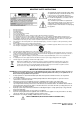
IMPORTANT SAFETY INSTRUCTIONS The lightning flash with arrowhead symbol, within an equilateral triangle is intended to alert the user to the presence of uninsulated “dangerous voltage“ within the product’s enclosure that may be of sufficent magnitude to constitute a risk of electric shock to persons. The exclamation point within an equilateral triangle is intended to alert the user to the presence of important operating and maintenance (servicing) instructions in the literature accompanying the appliance.
HF-Interference This equipment has been tested and found to comply with the limits for a Class B digital device, pursuant to Part 15 of the FCC Rules. These limits are designed to provide reasonable protection agains harmful interference in a residential installation. This equipment generates, uses and can radiate radio frequency energy and, if not installed and used in accordance with the instructions, may cause harmful interference to radio communications.
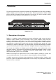
Introduction 1 Introduction First of all we want to express our thanks and offer our congratulations that you have selected the NetMax N8000 System Controller from Electro-Voice. Before operating the NetMax N8000 please read this instruction manual attentively to ensure that this device provides optimal performance and that damages due to improper use are avoided. N8000 front view 1.
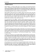
Introduction 1.2 N8000 features NetMax N8000 is an all-purpose digital audio system controller with outstanding performance features. A high quality system design provides excellent audio quality and clear sound, which is achieved by the application of high-end 24 Bit A/D and D/A converters with 120 dB volume range, high-quality input and output circuits in the analog domain and digital signal processing with optimized 48 bit double-precision algorithms.
Introduction The NetMax N8000 is equipped with all relevant interfaces by default in order to provide the connection to the network and external components. The Ethernet port makes the connection to existing building networks (intranet) and communication via the Internet possible. Ethernet is also the common connection between one or more N8000s and a PC with IRIS-Net software for the configuration, control and monitoring of a complete NetMax system.
Introduction 1.4 Installation instruction The N8000 has to be set up and installed so that both air supply and ventilation are ensured on both sides of the device. The direction of ventilation is from left to right when you look at the front faceplate. Devices with an opposing routing of air flow should not be installed in the same rack.
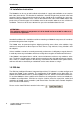
Introduction 1.6 Browser Interface Some of the configuration and operation options of the N8000 which are available in IRIS-Net are also provided by the N8000 browser interface. Any standard Internet browser with activated JavaScript and CSS can be utilized in order to use the browser interface. Please find the detailed information on the N8000 browser interface in the file N8000 browser manual in the IRIS-Net setup directory (\Documentation\NetMax).
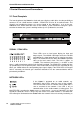
Control Elements and Connections 2 Control Elements and Connections 2.1 Front Faceplate The front faceplate of the N8000 has level and status displays and it offers also the possibility to connect a PC via a USB interface. SIGNAL / PEAK-LEDs exist for all 32 audio channels. The channels are combined to groups of 8 and assigned to the audio-slots 1 to 4 at the rear.
Control Elements and Connections clock master breaks down or is removed from the network, another N8000 will take over this function automatically. SYSTEM STATUS-LEDs These LEDs indicate device or system states. The READYLED is on when the device has booted after switch-on and when it is ready for operation. An illuminated FAULT-LED indicates an internal error in the N8000 or an error in the NetMax system. During the configuration of the N8000, it can be specified which errors should be displayed.
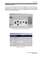
Control Elements and Connections 2.2 Rear Panel N8000 MODEL: MADE IN GERMANY AUDIO SLOT 3 AUDIO SLOT 1 AUDIO SLOT 4 AUDIO SLOT 2 BURNSVILLE, MN, U.S.A. C US 100-240 V~ 50-60 Hz/ 90 W N378 SERIAL: 170323 03150 10001 CONTROL PORT INPUTS 0-10V REMOTE RS-232 GND 1 2 3 4 10V REF PORT 1 ETHERNET STATUS RELAY OUTPUTS 2 3 4 5V/200mA CAN BUS PORT 2 There are all connections for analog and digital audio signals, control interfaces and the power supply at the rear panel of the N8000.
Control Elements and Connections N8000 automatically detects an installed network module. The module can be configured in the PC software IRIS-Net. ATTENTION: The N8000 has to be switched off if you want to change or install a module. You will find detailed instructions in the data sheet of the corresponding module. ETHERNET Interface A computer and/or other N8000 devices can be connected via the Ethernet interface for 100Base-TX / 10Base-T Ethernet networks.
Control Elements and Connections seconds. The duration of the flashing within these 2 seconds depends on the bus load. The higher the bus load is the longer the duration of the flashing within these two seconds will be. CONTROL PORT The CONTROL PORT contains four freely programmable control inputs, three freely programmable control outputs, one ready/fault output as well as reference connections for ground, +5 V and +10 V.
Preparations 3 Preparations 3.1 Mounting 1. Install the expansion cards. If you have purchased expansion cards (AI-1, AO-1, CM-1, DSP-1, etc.) for your N8000 system controller, please install them. In this regard, please note the paragraph page 15 as well as the installation instructions in the manuals which are enclosed to the expansion cards. 2. Connect the power cable. Please pay attention that the power switch of the N8000 (above the mains connector) is off. 3.
Preparations • 1 DSP expansion module (DSP-1) for the expansion of the storage capacity and signal processing ATTENTION: It is essential to switch off the N8000 if you want to install or change a module. You will find detailed instructions in the data sheet of the corresponding module. System expansion with analog/digital inputs or outputs There are four slots at the rear of the N8000 which are intended to expand the systems with analogue or digital inputs or outputs.
Preparations 3.3 Interface description Ethernet Interface By connecting the N8000 system controller via the Ethernet interface, the communication between the N8000 and one or several PC is possible. This allows the configuration of N8000 via IRIS-Net software. Furthermore, the whole connected system (consisting of N8000s and EV Precision Series Remote Control Amplifiers) can be operated and monitored.
Preparations The maximum length of a connected cable segment is 100 meters in both Ethernet standards, in which two twisted pairs are used in one cable. Category 3 (unshielded CAT-3) can be used for 10Base-T communication. Category 5 (CAT-5) must be used for 100Base-TX. Cat-5 cable is compatible with 10Base-T as well.
Preparations Assignment of CAN plug Colour Pin Name 2 CAN_GND 4 CAN_H (+) Blue 5 CAN_L (-) Blue striped 7 MONITOR BUS + Brown striped 8 MONITOR BUS - Brown T568A T568B Green Orange The CAN-bus makes it possible to use different data transmission rates, in which the boud rate is indirectly proportional to the length of the bus. If the network is only slightly extended, higher baud rates up to 500 kbit/s are possible.
Preparations USB connection The USB interface on the front panel of the N8000 uses the USB 1.1 standard. Accordingly, the low speed (1,5 MBit/s) and full speed (12 MBit/s) transfer rates are supported. According to USB specifications, the cable which is connected to this interface must not be longer than 5 meters. The USB interface of the N8000 is a USB-B (female) connector. The standard pin configuration can be seen in the following figure and table.
Preparations The pins of the RS-232 interface used in the N8000 are indicated in the following illustration and table. Connections which are not given are internally connected in the N8000 so that the communication between the N8000 and the connected device is possible via a software handshake system. The cable which is used for the connection should not be longer than 15 meters.
Preparations The following figure shows an example application for the "analogue circuit" on the control inputs of the N8000. A voltage which can be changed via a potentiometer is connected at the control input 1. The N8000 can be configured via IRIS-Net so that this voltage can be used to adjust a variable parameter, for example, adjusting the volume of an audio input or output. Control port with potentiometer An example for a "digital circuit" on a control input of N8000 is shown in the following figure.
Preparations ATTENTION: The maximum allowable current at the 5 V output is 200 mA. The two left connections of the RELAY OUTPUTS are the READY/FAULT output of the N8000. This floating output is closed when the N8000 is ready for operation and no error has occurred. It is possible in IRIS-Net to configure which kind of error causes the contact to be opened. Due to this feature, this contact is especially suitable for the integration of the N8000 in life safety systems (closed current principle).
Preparations N8000 Analog audio output cable, XLR (male) on Phoenix Digital audio connecting cable It is advisable to choose balanced cables (2 signal conductors + shield) with XLR connectors as digital audio connections. Although all N8000 digital audio inputs can be used unbalanced, balanced audio cable is the better choice.
Network configuration 4 Network configuration 4.1 Introduction The N8000 system controller can be connected to a TCP/IP-network via the Ethernet interface at its rear panel (see page 13). For further information on the principles of Ethernet and TCP/IP please see the chapter Ethernet principles on page 33 in the appendix of this document. The N8000 comes with the following network configurations from the factory: Parameter Value IP address 192.168.1.100 Subnet mask 255.255.255.0 Gateway 192.168.1.
Network configuration IP address 192.168.1.100 would exist four times in the network. Because of this, the preset IP address of three NetMax N8000s must be replaced with a unique address. Example of an Ethernet network with four N8000 It is advantageous and strongly recommended to list all devices used in the Ethernet network and IP addresses for changing the preset IP addresses of the N8000s. An example of such a list for the example system shown in the above illustration is given in the following.
Network configuration 4.2 Configuration Configuration and testing of an Ethernet connection with N8000 The purpose of this procedure is to build a connection between a PC and a N8000 with factory network settings (see page 25) via Ethernet and to check the proper function of this connection. In the following it is assumed that neither the PC nor the N8000 are connected with an existing network. 1. Click on Start > Control Panel > Network Connection. The window Network Connections appears.
Network configuration 3. Click on Properties in the context menu. The pop-up window Local Area Connection Properties appears. 4. Double click on Internet Protocol (TCP/IP). The pop-up window Internet Protocol (TCP/IP) Properties appears. 5. Choose the option Use the following IP address in the window. 6. Type 192.168.1.1 in the IP address input field. 7. Type 255.255.255.0 in the Subnet mask input field.
Network configuration 8. Close the window Internet Protocol (TCP/IP) Properties by clicking on the OK button. The IP configuration of the PC is now complete. In the following steps the connection of the PC with the N8000 will be established and checked. 9. Connect the network connection of your PC to the Ethernet interface of the N8000 directly with a crossover cable, or with a patch cable and a hub/switch.
Network configuration 12. Enter ping 192.168.1.100 and tap the return button. The PC is now checking the connection with the N8000. For this four network packets are sent to the N8000 via Ethernet then the N8000 has to confirm these packets. If the Ethernet connection is successful, no packets get lost. Therefore, 0% loss is stated in the ping statistics.
Appendix 5 Appendix 5.1 Application Example Installation in a multi-purpose hall The following figure shows an example for the application of a N8000 system controller in a multipurpose hall. Four microphones, one CD player and one tuner are the connected signal sources. Both active and passive speakers are used for the sound reinforcement.
Appendix 5.2 Troubleshootings Problem: It is not possible to establish a connection with the N8000 via IRIS-Net.
Appendix Check Network Configuration of PC: Check the network configuration of the used PC. Remember that the network part of the used IP addresses that is used and the subnet mask of the PC and the N8000 have to be identical. Ruling Out Duplicate IP-Adresses: It is possible that the same IP address is allocated twice if there are more devices in an Ethernet network and if the IP addresses are allocated manually.
Appendix • 100Base-TX (IEEE 802.3u): Two twisted wire pairs are used for the connection (see above). However, in this case, a CAT-5 cable has to be used. 100Base-TX has a transfer rate of 100 MBit/s and is the standard Ethernet implementation nowadays. IP addresses Diverse network protocols can be used for the communication of the devices connected to the Ethernet network. The N8000 uses the TCP/IP protocol, thus, it is an IP network device.
Appendix For example, a network could e.g. split the 4 Byte (32 bit) of an IP address in a 3 Byte long network part and in 1 Byte long host part. The exact partitioning between network part and host part is given in the form of subnet masks. In this case, the partitioning of the first 24 bits or the last 8 bits would be made because of the subnet mask 255.255.255.0. The CIDR notation which is designed to display a subnet mask is an alternative to the dotted decimal notation.
Appendix 5.4 CAN-Bus Principles The network topology used by the CAN bus is based on the so-called “bus or line topology”, i.e. all participants are connected via a single two-wire cable (Twisted-Pair cable, shielded or unshielded) with the cabling running from one participant on the bus to the next, allowing unlimited communication among all devices. In general, it does not matter if the bus member is a power amplifier, a N8000 or a UCC1 USB-CAN converter.
Appendix bus signals. The internal running time of the repeaters of approx. 150 ns corresponds to an extension of the bus over approx. 45 meters. • Creation of alternative network topologies By using one or several repeaters, not only the above-mentioned bus topology, but the creation of other network topologies are also possible. In the following figure a star topology from three independent CAN bus systems is given as example. The three CAN buses are connected via two repeaters.
Appendix System Examples The following illustrations show examples of the data-bus wiring for different sizes of CAN-bus networks.. System with 5 power amps and 1 N8000 at the beginning of the bus. Termination plugs at the N8000 (first unit on the bus) and at amp 5 (last unit on the bus). . System with 2 amp-racks and 1 N8000/PC in the middle. Termination plugs at power amp 6 (first unit on the bus) and power amp 12 (last unit on the bus).
Appendix Performance Specifications According to the ISO 11898-2 standard, CAN-bus data transfer cabling has to be carried out using Twisted-Pair cables with or without shielding providing a characteristic impedance of 120 Ω. Both ends of a CAN-bus need to be terminated with 120 Ω termination-plugs. The maximum bus-length depends on the actual data transfer rate, the kind of data transfer cable being used, as well as the total number of participants on the bus.
Appendix 5.
6.
SIGNAL PROCESSING Sample Rate Data Format Signal Processing INTERFACES Ethernet CAN RS-232 USB GPIO Control Port N8000 GENERAL SPECIFICATIONS Power Supply Power Consumption Safety Class Cooling Operating Temperature Range Dimensions (W x H x D) Weight MODULES / OPTIONS AI-1 Analog Input Module AO-1 Analog Output Module CM-1 CobraNet™ Module DSP-1 DSP Extension Module MI-1 Microphone Input Module DI-1 Digital Input Module 42 NetMax N8000 System Controller Owner’s manual / Bedienungsanleitung 48 kHz int
6.2 Block Diagram/Blockschaltbild AUDIO CARDS AUDIO CARDS 8 Channels AUDIO CARDS 8 Channels Analog I/O AUDIO MODULES 8 Channels Analog DigitalI/O I/O DigitalI/O I/O 8Analog Channels Digital Analog I/OI/O AUDIO NETWORK MODULES 32 Inputs / 32 Outputs Digital I/O AUDIO SLOT 1 AUDIO SLOT 2 AUDIO SLOT 3 AUDIO SLOT 4 AUDIO NETWORK PORT Audio Out (4x8 Channels) Audio In (4x8 Channels) 12.
6.
Notes
Notes
Notes
Notes USA: Telex Communications Inc., 12000 Portland Ave. South, Burnsville, MN 55337, Phone: +1 952-884-4051, FAX: +1 952-884-0043 Germany: EVI Audio GmbH, Hirschberger Ring 45, D 94315, Straubing, Germany, Phone: +49 9421-706 0, FAX: +49 9421-706 265 France: EVI Audio France, Parc de Courcerin, Allée Lech Walesa, 77185 Lognes, France, Tél : +33 1 6480 0090, FAX: +33 1 6006 5103 Subject to change withou prior notice. Printed in Germany www.electro-voice.de V1.