
EB-M Installation Manual


04/15/2019 13 BI518
OPERATIONAL TIPS
Electric/Standby Switch
If this system does not have a standby operating (gas or oil) boiler, this
switch must always be in the ELECTRIC position.
To activate standby boiler, simply position front panel switch to STANDBY.
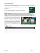
Front Panel Monitor Lights
190°F AUTO RESET LIMIT, red – this will only
illuminate when the vessel hi-limit opens due to
excessive high water temperature. This hi-limit is
self-resetting.
BOILER POWER, green – basically this is
illuminated at all times. It represents 24-volt power
source, good fuse, controller logic is operational,
and a good outlet sensor. If the outlet sensor is
inoperative, incorrectly wired, or malfunctioning;
this green monitor LED should be pulsing (see
Troubleshooting section).
ELECTRIC MODE, yellow – when illuminated
the system is in the electric mode. If it is not
illuminated the utility load control receiver is in the
interrupt or on-peak mode. If there is an optional or
remote standby switch, the status of the standby
switch is also monitored by this yellow LED.
THERMOSTAT CALL, red – indicates a remote
switch closure (thermostat or zoning end switch) is
closed between terminals R and W.
Inside Control Board Monitor Lights
STAGES, red – these four LED’s indicate which electric element stages are on and active.