
User Manual

8
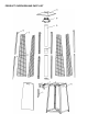
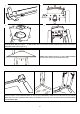
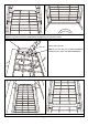
STEP 4: Attach the FLAME SCREEN (B) to the top of assembled SUPPORT BAR and fix using two M5 SCREWS
and WASHERS (BB) (See Figure 1, 2). Repeat this step to connect the FLAME SCREEN (B) to other 3 assembled
SUPPORT BARS. (See Figure 3, 4)
STEP 5: Place REFLECTOR (A) on the FLAME SCREEN
(B) and secure using four M5 CAP NUTS (AA).
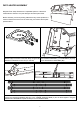
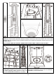
STEP 6: Unscrew the eight M5 Screws and Washers preassembled on top of the MAIN BODY (K).
Place the bottom of the SUPPORT BARS on the top of the MAIN BODY. Make sure to match the top of the MAIN
BODY with the on the SUPPORT BAR. Match the threaded hole and fix each connection with 2pcs M5 SCREWS
and WASHERS (BB)
1
2
3
4