
User Manual

6
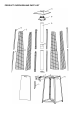
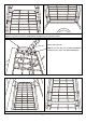
PART
PART NAME
PICTURE
QTY
A
REFLECTOR
1
B
FLAME SCREEN
1
C
MESH GUARD - UPPER
4
D
MESH GUARD - LOWER
4
E
SUPPORT BAR - UPPER
4
F
SUPPORT BAR - LOWER
4
G
GLASS TUBE
2
H
CONNECTOR
(Glass Tube Connector or Stainless
Steel Connector dependent on model)
or
1
I
RUBBER RING
1
J
BURNER ASSEMBLY
1
K
MAIN BODY
1
L
CHAIN (ASSEMBLED WITH DOOR)
1
M
WHEEL
2
N
BRACKET
1
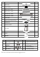
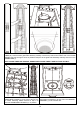
PART
PART NAME
PICTURE
QTY
DESCRIPTION
AA
M5 CAP NUT
4
To connect reflector and flame
screen
BB
STANDARD
SCREWS &
WASHER
12*
M5 x 8 screw & M5 washer
To fix burner assembly on the tank
housing assembly.
CC
M6 NUT & WASHERS
4*
For attaching the Wheels
DD
M6 SCREWS
4*
For attaching the Wheels
Note: Some of the fittings may be provided pre attached to the unit.