
Installation and Operation Manual


4) Remove the left strain relief strap from the inside of the body.
5) Pull the wire down through the strain relief nut and remove the strain relief nut from the plug cable.
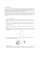
Flip the cosmetic cover upward to separate from the body. Insert the new wire through the conduit, then into the
body of the charger.
NOTE: The conductor size shall be enough for 6 AWG.
During installation be sure to use proper personal protective equipment and do not touch wiring terminals with
your fingers
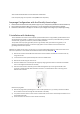
1. Crimp insulated wire ferrules onto each supply power wire, including ground. Follow the ferrule
manufacturer’s instructions for crimping the ferrules onto each wire.
2. Insert each ferrule terminated wire in the terminal block, ensuring the wires are located properly.
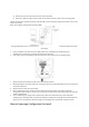
1. Tighten terminal block screws to 33-40 in-lb (3.73-4.5 N-M) of torque.
2. Reinstall and tighten the strain relief strap, ensuring the wires are not strained between the strain relief strap
and the terminal block.
3. Tighten the strain relief nut to the conduit.
4. Prior to replacing the cover, place the wire connecting the charger and the cover back into the wire
management clip and secure it. Failure to do so may result in interference with the LED signal and erratic LED
indicator light behavior.
5. Prior to reattaching the charger cover, work with your electrician to determine the proper method for
configuring your amperage rating. It is always preferable to configure the amperage via the Electrify America
App. If you are not required to manually configure the amperage, go to the Reattach The Cover section.
Manual Amperage Configuration (Optional)