
Operation Manual


BNET (a BSX ™ Product) Operation Manual
Office: 972 (0) 73-3354727 Fax : 972 (0) 733354291 Page 10 of 17
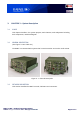
No.
Item/Connector
Type
Description
1.
Datal J10
Connector
Connect data cable that Transmits and receives data via Ethernet
communication.
4.
Audio J12
Connector
Connect audio cable that Transfers audio signals:
• Earphones out
• PTT input
• Speaker out
5.
ANT J2
RF
connector
Connects the UHF Antenna
6.
PWR J9
Connector
Input 24 VDC power for unit operation
10.
On/Off switch
Switch
Turns on/ off the BNET
11.
Indication
lights
Led
Description of the BNET from left to right:
1. Green light indicates if the BNET is on/ off.
2. Middle and right light are inactive in Blacksky V1.
12.
Conf-preset
Switch
Enables switching between different presets. Each preset can be
are logical networks (voice groups).
13.
Zeroize
Switch
Deletes all BNET encryption key data not in use.
14.
GPS J8
RF
connector
Connects the GPS Antenna
Table 3- 1: BNET Vehicular