Guide V1.0 Starter Kit for Arduino Contents Arduino IDE (Integrated Development Environment) .......................................................... 3 Introduction ................................................................................................................... 3 Operation demo ................................................................................................................... 3 Step 1: Install the Arduino Software (IDE) ...............................................
Guide V1.0 Lesson 14: 1 digit 7 Segment Displays ............................................................... 46 Lesson 15: 4 digit 7 Segment Displays ............................................................... 49 Lesson 16: Heart-shaped display experiment .................................................... 51 Lesson 17: Sweep ............................................................................................... 55 Lesson 18: Knob .........................................................
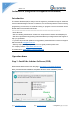
Guide V1.0 Arduino IDE (Integrated Development Environment) Introduction The Arduino Software (IDE) is easy-to-use for beginners, yet flexible enough for advanced users to take advantage of as well. For teachers, it's conveniently based on the Processing programming environment, so students learning to program in that environment will be familiar with how the Arduino IDE works.
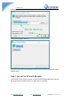
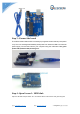
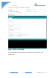
Guide V1.0 Choose the components to install and click “next” button. Choose the installation directory. The process will extract and install all the required files to execute properly the Arduino Software (IDE) Step 2: Get an Uno R3 and USB cable In this tutorial, you're using an Uno R3. You also need a standard USB cable (A plug to B plug): the kind you would connect to a USB printer, for example. Email: keen@elecrow.com Web: www.elecrow.
Guide V1.0 Step 3: Connect the board The USB connection with the PC is necessary to program the board and not just to power it up. The Uno and Mega automatically draw power from either the USB or an external power supply. Connect the board to your computer using the USB cable. The green power LED (labelled PWR) should go on. Step 4: Open Lesson 1: LED blink Open the LED blink example sketch: CD > For Arduino>Demo Code>Lesson1-LED_bink>led_blink. Email: keen@elecrow.com Web: www.elecrow.
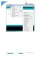
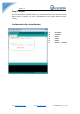
Guide V1.0 Step 5: Select your board You'll need to select the entry in the Tools > Board menu that corresponds to your Arduino board. Email: keen@elecrow.com Web: www.elecrow.
Guide V1.0 Selecting an Arduino/Genuino Uno. Email: keen@elecrow.com Web: www.elecrow.
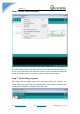
Guide V1.0 Step 6: Select your serial port Select the serial device of the board from the Tools | Serial Port menu. This is likely to be COM3 or higher (COM1 andCOM2 are usually reserved for hardware serial ports). To find out, you can disconnect your board and re-open the menu; the entry that disappears should be the Arduino board. Reconnect the board and select that serial port. Step 7: Upload the program Now, simply click the "Upload" button in the environment.
Guide V1.0 Step 8: Result A few seconds after the upload finishes, you should see the pin 13 (L) LED on the board start to blink (in orange). If it does, congratulations! You've gotten Arduino up-andrunning. Arduino interface introduction A B C D E F Email: keen@elecrow.com Web: www.elecrow.
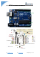
Guide V1.0 Arduino UNO R3 hardware introduction Email: keen@elecrow.com Web: www.elecrow.
Guide V1.0 How to add library files Step 1: Add library file: Sketch>Include Library>Add.ZIP Library Step 2: Select your library file compression package on the demo code file, as follows: Email: keen@elecrow.com Web: www.elecrow.
Guide V1.0 Step 3: Finish. Email: keen@elecrow.com Web: www.elecrow.
Guide V1.0 Learning materials Ebook Introduction The E-book about Arduino what we provided for you is carefully selected and comprehensive, it specially aims at solving the problems when you make projects such as syntax analysis, program optimization and so on. If you have any questions about the projects what we provided, you can also refer the content of e-books. Path: \For Arduino \Ebook Language Reference https://www.elecrow.com/wiki/ http://wiring.org.co/reference/ https://www.arduino.
Guide V1.0 Lesson 1: LED blink Overview The LED is designed for the beginners of Arduino. It is the best way to step into the from RPI what it’s I/O pins. The LED is the best choice to help you learn I/O pins. Specification Pin definition LED Long pin Short pin -> -> UNO R3 +5V GND Hardware required Material diagram Email: keen@elecrow.com Material name Number 220/330Ω resistor 1 LED 1 USB Cable 1 Web: www.elecrow.
Guide V1.0 UNO R3 1 Breadboard 1 Jumper wires Several Bread board schematic All the tie points (indicated in the picture) of the different colors are connected together. Email: keen@elecrow.com Web: www.elecrow.
Guide V1.0 Connection diagram Note:The longest LED of the pin is connected to the digital signal port 13(D13). Compile and upload Tips: Refer to the operation demo (Step4 to Step8). Language reference Tips:click on the following name to jump to the web page. Email: keen@elecrow.com Web: www.elecrow.
Guide V1.0 If you fail to open, use the Adobe reader to open this document. int setup() pinMode() OUTPUT loop() HIGH LOW digitalWrite() digitalRead() delay() ; (semicolon) {} (curly braces) = (assign) // (comment) Application effect Turns on an LED on for one second, then off for one second, repeatedly. Lesson 2: LED trailing effects Overview This lesson will teach you how to show 6 LED trailing effects. Email: keen@elecrow.com Web: www.elecrow.
Guide V1.0 Specification Pin definition LED Long pin Short pin -> -> UNO R3 +5V GND Hardware required Material diagram Email: keen@elecrow.com Material name Number 220/330Ω resistor 6 LED 6 USB Cable 1 UNO R3 1 Breadboard 1 Jumper wires Several Web: www.elecrow.
Guide V1.0 Connection diagram Note:The longest LED of the pin is connected to the digital signal port *(D*). Compile and upload Tips: Refer to the operation demo (Step4 to Step8). Language reference Tips:click on the following name to jump to the web page. If you fail to open, use the Adobe reader to open this document. int pinMode() OUTPUT for() HIGH LOW digitalWrite() Email: keen@elecrow.com Web: www.elecrow.
Guide V1.0 delay() Application effect You'll see all the LEDs will turn on/off regularly. Lesson 3: Traffic light Overview The experiment shows the effect of the simulation of traffic lights. Specification Pin definition LED Long pin Short pin -> -> UNO R3 +5V GND Hardware required Material diagram Email: keen@elecrow.com Material name Number 220/330Ω resistor 3 Web: www.elecrow.
Guide V1.0 Yellow LED 1 Green LED 1 Red LED 1 USB Cable 1 UNO R3 1 Breadboard 1 Jumper wires Several Connection diagram Note:The longest LED of the pin is connected to the digital signal port *(D*). Compile and upload Tips: Refer to the operation demo (Step4 to Step8). Email: keen@elecrow.com Web: www.elecrow.
Guide V1.0 Language reference Tips:click on the following name to jump to the web page. If you fail to open, use the Adobe reader to open this document. pinMode() OUTPUT INPUT for() HIGH LOW digitalWrite() delay() < (less than) ++ (increment) Application effect The green light flashes for 5 seconds, then the yellow light flashes 3 times, and then the red light 5 seconds, the formation of a cycle. And then repeat the cycle. This experiment shows the effect of the simulation of traffic lights.
Guide V1.0 Resistance Value: 10K ohm; Adjustment Type: Top Adjustment Pin definition Null Hardware required Material diagram Material name Number 10KΩ potentiometer 1 USB Cable 1 UNO R3 1 Breadboard 1 Jumper wires Several Connection diagram Note:The middle pin of the potentiometer is connected to the analog port 0(A0). Email: keen@elecrow.com Web: www.elecrow.
Guide V1.0 Compile and upload Tips: Refer to the operation demo (Step4 to Step8). Language reference Tips:click on the following name to jump to the web page. If you fail to open, use the Adobe reader to open this document. digitalWrite() analogRead() Application effect By turning the shaft of the potentiometer, you change the amount of resistance on either side of the center pin (or wiper) of the potentiometer.
Guide V1.0 This example demonstrates the use of analog output (Pulse Width Modulation (PWM)) to fade an LED. PWM is a technique for getting an analog-like behavior from a digital output by switching it off and on very fast and with different ratio between on and off time. Specification Pin definition LED Long pin Short pin -> -> UNO R3 +5V GND Hardware required Material diagram Email: keen@elecrow.
Guide V1.0 Connection diagram Note:An LED connected to digital output pin 5 (D5) through a 220 ohm resistor. Compile and upload Tips: Refer to the operation demo (Step4 to Step8). Language reference Tips:click on the following name to jump to the web page. If you fail to open, use the Adobe reader to open this document. += (add assign) -= (subtract assign) Email: keen@elecrow.com Web: www.elecrow.
Guide V1.0 <= (less than or equal to) >= (greater than or equal to) Application effect You'll see that LED has the effect of breathing light. Lesson 6: Button Overview Pushbuttons or switches connect two points in a circuit when you press them. This example turns on the built-in LED on pin 13 when you press the button. Specification Size: 6 x 6 x 5mm Temperature: -30 ~ +70 Centigrade Pin definition It is the definition of Button pin: Email: keen@elecrow.com Web: www.elecrow.
Guide V1.0 Hardware required Material diagram Material name Button Number 10KΩ resistor 1 USB Cable 1 UNO R3 1 Breadboard 1 Jumper wires Several 1 Connection diagram Connect three wires to the board. The first two, red and black, connect to the two long vertical rows on the side of the breadboard to provide access to the 5 volt supply and ground. The third wire goes from digital pin 2 to one leg of the pushbutton.
Guide V1.0 leg of the button connects to the 5 volt supply. When the pushbutton is open (unpressed) there is no connection between the two legs of the pushbutton, so the pin is connected to ground (through the pull-down resistor) and we read a LOW. When the button is closed (pressed), it makes a connection between its two legs, connecting the pin to 5 volts, so that we read a HIGH.
Guide V1.0 Lesson 7: Responder experiment Overview This lesson will teach you how to be a responder. Specification Button : Size: 6 x 6 x 5mm LED: Temperature: -30 ~ +70 Centigrade Pin definition Is the definition of Button pin: Hardware required Material diagram Email: keen@elecrow.com Material name Web: www.elecrow.
Guide V1.0 Button 4 LED 3 220/330Ω resistor 3 10KΩ resistor 4 USB Cable 1 UNO R3 1 Breadboard 1 Jumper wires Several Connection diagram Note: Button using 10KΩ resistor, LED use 220/330Ω resistor. Email: keen@elecrow.com Web: www.elecrow.
Guide V1.0 Compile and upload Tips: Refer to the operation demo (Step4 to Step8). Language reference Tips:click on the following name to jump to the web page. If you fail to open, use the Adobe reader to open this document. digitalRead() == (equality) Application effect Whichever button is pressed first, then the corresponding LED will be on! If you want to reset, hit the Reset button. Lesson 8: Active buzzer Overview This is an active buzzer experiment.
Guide V1.0 Long pin Short pin -> -> D5 GND Hardware required Material diagram Material name Number Active buzzer 1 USB Cable 1 UNO R3 1 Breadboard 1 Jumper wires Several Connection diagram Note:The longest active buzzer of the pin is connected to the digital signal port 5 (D5). Email: keen@elecrow.com Web: www.elecrow.
Guide V1.0 Compile and upload Tips: Refer to the operation demo (Step4 to Step8). Language reference Tips:click on the following name to jump to the web page. If you fail to open, use the Adobe reader to open this document. digitalWrite() pinMode() Application effect When the upload process is complete, the buzzer rings. Lesson 9: Passive buzzer Overview Specification Working Voltage: 3V/5V Resistance: 16Ohm Resonance Frequency: 2KHZ Email: keen@elecrow.com Web: www.elecrow.
Guide V1.0 Pin definition Passive Buzzer Long pin Short pin -> -> UNO R3 D5 GND Hardware required Material diagram Material name Number Passive buzzer 1 USB Cable 1 UNO R3 1 Breadboard 1 Jumper wires Several Connection diagram Email: keen@elecrow.com Web: www.elecrow.
Guide V1.0 Compile and upload Tips: Refer to the operation demo (Step4 to Step8). Language reference Tips:click on the following name to jump to the web page. If you fail to open, use the Adobe reader to open this document. #define tone() Application effect When the upload process is complete, the buzzer sounds for 2 seconds. Lesson 10: RGB LED Overview In this lesson, you will learn how to use a RGB (Red Green Blue) LED with an Arduino.
Guide V1.0 Size(Approx): 5 x 35mm/ 0.2" x 1.37" (D * L) Forward Voltage: 3.0-3.4V Luminous Intensity: 12000-14000mcd Pin definition It is the definition of RGB LED pin: RGB LED R GND G B -> -> -> -> UNO R3 D11 GND D10 D9 Hardware required Material diagram Email: keen@elecrow.com Material name RGB LED Number 220Ω/330Ω resistor 3 USB Cable 1 UNO R3 1 Breadboard 1 Jumper wires Several Web: www.elecrow.
Guide V1.0 Connection diagram Note: The longest pin of the RGB LED is connected to the GND. Compile and upload Tips: Refer to the operation demo (Step4 to Step8). Language reference Tips:click on the following name to jump to the web page. If you fail to open, use the Adobe reader to open this document. analogWrite() #define Email: keen@elecrow.com Web: www.elecrow.
Guide V1.0 Application effect When the program is uploaded, you will see the LED loop emit 7 different colors of light. Lesson 11: Making sounds Overview In this lesson, you will learn how to make sounds with your Arduino. First you will make the Arduino play a 'musical' scale and then combine this with a photocell, to make a Thereminlike instrument that changes the pitch played as you wave your hand over the photocell.
Guide V1.0 Hardware required Material diagram Material name Number Photoresistor 1 Passive buzzer 1 10KΩ resistor 1 USB Cable 1 UNO R3 1 Breadboard 1 Jumper wires Several Connection diagram Note: Photoresitor`s pin is not divided into positive and negative polarity Email: keen@elecrow.com Web: www.elecrow.
Guide V1.0 Compile and upload Tips: Refer to the operation demo (Step4 to Step8). Try changing the value 4 in the line below to lower and higher values. //int pitch = 200 + reading / 4; We simply take an analog reading from A0, to measure the light intensity. This value will be in the range of something like 0 to 700. We add 200 to this raw value, to make 200 Hz the lowest frequency and simply add the reading divided by 4 to this value, to give us a range of around 200Hz to 370Hz.
Guide V1.0 Color: Black Rated Power: 0.05W Resistance Value: 10k Resistance Tolerance: H (±3%) B Value: 3950K Pin Pitch: 1.5mm / 0.059" Pin definition Nonpolar Hardware required Material diagram Email: keen@elecrow.com Material name Number Thermistor 1 10KΩ resistor 1 USB Cable 1 UNO R3 1 Breadboard 1 Jumper wires Several Web: www.elecrow.
Guide V1.0 Connection diagram Note: Thermistor `s pin does not distinguish between positive and negative poles. Compile and upload Tips: Refer to the operation demo (Step4 to Step8). And open the serial port. Email: keen@elecrow.com Web: www.elecrow.
Guide V1.0 Language reference serial DEC Application effect After uploading the program, open the serial port monitor, you will see a series of temperature values Lesson 13: Tilt switch Overview This is a very simple switch experiment. Specification Pin definition Nopolarity. Hardware required Material diagram Email: keen@elecrow.com Material name Number Ball switch 1 LED 1 Web: www.elecrow.
Guide V1.0 220/330Ω resistor 1 10KΩ resistor 1 USB Cable 1 UNO R3 1 Breadboard 1 Jumper wires Several Connection diagram Email: keen@elecrow.com Web: www.elecrow.
Guide V1.0 Note:The longest LED of the pin is connected to the digital signal port 11 (D11). Ball switch`s pin is not divided into positive and negative polarity. Compile and upload Tips: Refer to the operation demo (Step4 to Step8). Language reference Tips:click on the following name to jump to the web page. If you fail to open, use the Adobe reader to open this document. If() else Application effect LED light up when you lean or knock on ball switch.
Guide V1.0 Specification Null Pin definition Hardware required Material diagram Material name Number 1 digit LED Segment Displays 1 220/330Ω resistor USB Cable 1 UNO R3 1 Breadboard 1 Jumper wires Several Connection diagram Email: keen@elecrow.com Web: www.elecrow.
Guide V1.0 Note:Pay attention to the direction of digital tube. Connection: UNO R3 SEG D3 -> C D4 -> D D5 -> E D6 -> G D7 -> F D8 -> A D9 -> B GND -> COM Compile and upload Tips: Refer to the operation demo (Step4 to Step8). Email: keen@elecrow.com Web: www.elecrow.
Guide V1.0 Language reference array Application effect You will see the number on the digital tube increased from 0 to 9. Lesson 15: 4 digit 7 Segment Displays Overview This experiment is similar with the LED experiment, the same is the control of LED, but the experiment can achieve time counting function. Specification Null Pin definition Email: keen@elecrow.com Web: www.elecrow.
Guide V1.0 Hardware required Material diagram Material name Number 4 digit LED Segment Displays 1 220/330Ω resistor 8 USB Cable 1 UNO R3 1 Breadboard 1 Jumper wires Several Connection diagram Email: keen@elecrow.com Web: www.elecrow.
Guide V1.0 Note: Pay attention to the direction of digital tube. Compile and upload Tips: Refer to the operation demo (Step4 to Step8). Language reference Long switch() case Application effect The time counting function, you will see the number of digital tube display increasingly. Lesson 16: Heart-shaped display experiment Overview This lesson will teach you how to use an 8*8 dot matrix to display a beating heart animation. Specification Please view 1588 ABxx.pdf. Path: \Datasheet\1588 ABxx.
Guide V1.0 Pin definition Hardware required Material diagram Material name Number 8*8 Dot-matrix Display 1 220/330Ω resistor 8 USB Cable 1 UNO R3 1 Breadboard 1 Jumper wires Several Connection diagram Email: keen@elecrow.com Web: www.elecrow.
Guide V1.0 Connection: pin1 ->D3 pin2 ->D4 pin3 ->A2 Need connection resistance. pin4 ->A1 Need connection resistance. pin5 ->D5 pin6 ->A0 Need connection resistance. pin7 ->D6 pin8 ->D7 pin9 ->D11 Email: keen@elecrow.com Web: www.elecrow.
Guide V1.0 pin10->D10 pin11- >D9 pin12 ->D8 pin13 ->A3 pin14 ->D2 pin15 ->A4 pin16 ->A5 Need connection resistance. Need connection resistance. Need connection resistance Need connection resistance. Need connection resistance. Note: Some pin ports need connection resistance. Compile and upload Tips: Refer to the operation demo (Step4 to Step8). By modifying the “unsigned char table1[8][8] = {}” or “unsigned char table2[8][8] = {}” function, you can display different animation.
Guide V1.0 Lesson 17: Sweep Overview Sweeps the shaft of a RC servo motor back and forth across 180 degrees. This example makes use of the Arduino servo library. Specification Please view SG90Servo-datasheet.pdf. Path: \ Datasheet\ SG90Servo-datasheet.pdf Pin definition Hardware required Material diagram Email: keen@elecrow.com Material name 9g Servo Number USB Cable 1 UNO R3 1 Breadboard 1 Web: www.elecrow.
Guide V1.0 Jumper wires Several Connection diagram Compile and upload Tips: Refer to the operation demo (Step4 to Step8). Language reference null Application effect You will see the servo motor turning 180 degrees back and forth. Email: keen@elecrow.com Web: www.elecrow.
Guide V1.0 Lesson 18: Knob Overview Control the position of a RC (hobby) servo motor with your Arduino and a potentiometer. This example makes use of the Arduino servo library. Specification 9G servo: please view SG90Servo-datasheet.pdf. Path: \Datasheet\ SG90Servo-datasheet.pdf Potentiometer: Resistance Value: 10K ohm; Adjustment Type: Top Adjustment Pin definition 9G servo: Potentiometer: Null Hardware required Material diagram Email: keen@elecrow.
Guide V1.0 USB Cable 1 UNO R3 1 Breadboard 1 Jumper wires Several Connection diagram Email: keen@elecrow.com Web: www.elecrow.
Guide V1.0 Note: The middle pin of the potentiometer is connected to the analog port 0(A0). Compile and upload Tips: Refer to the operation demo (Step4 to Step8). Language reference Tips:click on the following name to jump to the web page. If you fail to open, use the Adobe reader to open this document. Map() Application effect When the rotary potentiometer, the servo motor also with the rotation.
Guide V1.0 Pin definition Hardware required Material diagram Material name Number Step motor 1 ULN2003 step motor driver board 1 USB Cable 1 UNO R3 1 Breadboard 1 Female to male Jumper wires 6 Jumper wires Several Connection diagram Connection: ULN2003 IN4 -> Email: keen@elecrow.com UNO R3 D2 Web: www.elecrow.
Guide V1.0 IN3 IN2 IN1 ‘-’ ‘+’ -> -> -> -> -> D3 D4 D5 GND +5V Compile and upload Tips: Refer to the operation demo (Step4 to Step8). Language reference Note:click on the following name to jump to the web page. If you fail to open, use the Adobe reader to open this document. Stepper myStepper = Stepper(steps, pin1, pin2, pin3, pin4) stepper.setSpeed() stepper.step() Application effect The motor will step one step at a time, very slowly.
Guide V1.0 Specification Please view “Stepper-Motor.pdf” Path: \Datasheet\ Stepper-Motor.pdf Pin definition Hardware required Material diagram Email: keen@elecrow.com Material name Number Step motor 1 ULN2003 step motor driver board 1 10KΩ potentiometer 1 USB Cable 1 UNO R3 1 Breadboard 1 Female to male Jumper wires 6 Jumper wires Several Web: www.elecrow.
Guide V1.0 Connection diagram Note: The middle pin of the potentiometer is connected to the analog port 0(A0). Compile and upload Tips: Refer to the operation demo (Step4 to Step8). Email: keen@elecrow.com Web: www.elecrow.
Guide V1.0 Language reference Note:click on the following name to jump to the web page. If you fail to open, use the Adobe reader to open this document. Stepper myStepper = Stepper(steps, pin1, pin2, pin3, pin4) stepper.setSpeed() stepper.step() Application effect The motor will rotate in a clockwise direction. The higher the potentiometer value, the faster the motor speed.
Guide V1.0 Hardware required Material diagram Material name Relay module Number Button 1 10KΩ resistor 1 USB Cable 1 UNO R3 1 Breadboard 1 Jumper wires Several 1 Connection diagram Email: keen@elecrow.com Web: www.elecrow.
Guide V1.0 Compile and upload Tips: Refer to the operation demo (Step4 to Step8). Language reference Tips:click on the following name to jump to the web page. If you fail to open, use the Adobe reader to open this document. const millis() Application effect When the button is pressed, the state of the relay will be changed. Lesson 22: Touch lamp Overview This is a touch sensor to control the LED lamp experiment, it can control each LED light, but also can achieve the effect of breathing light.
Guide V1.0 Pin definition Touch Sensor GND VCC SIG -> -> -> UNO R3 GND +5V D2 Hardware required Material diagram Email: keen@elecrow.com Material name Number Touch Sensor 1 LED 3 220/330Ω resistor 3 USB Cable 1 UNO R3 1 Breadboard 1 Jumper wires Several Web: www.elecrow.
Guide V1.0 Connection diagram Note:The longest LED of the pin is connected to the digital signal port. Compile and upload Tips: Refer to the operation demo (Step4 to Step8). Email: keen@elecrow.com Web: www.elecrow.
Guide V1.0 Language reference Tips:click on the following name to jump to the web page. If you fail to open, use the Adobe reader to open this document. attachInterrupt switch(case) Application effect Through the touch panel, you can control the LED light. Lesson 23: Flame alarm system Overview This lesson will teach you how to make a Flame alarm system. It can detect flame. Specification Null Pin definition Email: keen@elecrow.com Web: www.elecrow.
Guide V1.0 Hardware required Material diagram Material name Number Active buzzer 1 Flame Sensor 1 10KΩ resistor 1 USB Cable 1 UNO R3 1 Breadboard 1 Jumper wires Several Connection diagram Flame sensor UNO R3 Short Pin -> +5V Long Pin -> A0 PassiveBuzzer -> D6 Note:The short pin of the Flame sensor is connected to +5v. Compile and upload Tips: Refer to the operation demo (Step4 to Step8). Language reference Null Email: keen@elecrow.com Web: www.elecrow.
Guide V1.0 Application effect We can simulate a flame environment. Turn on the lighter and then near the flame sensor, you will hear the buzzer sound. Lesson 24: Ultrasonic ranging Overview This is the experimental use of ultrasonic module (HCSR04) test distance. Ultrasonic module is generally used in the robot. Specification Please view “HCSR04.pdf” Path: \Datasheet\ HCSR04.
Guide V1.0 Jumper wires Several Connection diagram Connection: HC SR04 Vcc Trig Echo Gnd -> -> -> -> UNO R3 VCC D2 D3 GND Compile and upload Tips: Refer to the operation demo (Step4 to Step8). Language reference Tips:click on the following name to jump to the web page. If you fail to open, use the Adobe reader to open this document. delayMicroseconds() Application effect Open the serial port monitor, and you will see the data returned by the ultrasonic module. Email: keen@elecrow.com Web: www.
Guide V1.0 Lesson 25: IR remote control experiment Overview This is an experiment on the infrared reception. This experiment uses the infrared decoder, which involves the content of complex, so only the introduction of the use of methods. Specification IR Receiver: Please view “IR Receiver-datasheet.pdf” Path: \Datasheet\ IR Receiver-datasheet.pdf Pin definition Hardware required Material diagram Email: keen@elecrow.com Material name Web: www.elecrow.
Guide V1.0 IR Remote 1 IR Receiver 1 USB Cable 1 UNO R3 1 Breadboard 1 Jumper wires Several Connection diagram Note: Please view Pin definition. Connection UNO R3 IR Receiver D2 -> OUT GND -> GND +5V -> VCC Compile and upload Tips: Refer to the operation demo (Step4 to Step8). If you have added the library, skip it. Otherwise, you need to add the IRremote to the Arduino library file directory, otherwise the compiler does not pass. Please refer to ‘How to add library files’.
Guide V1.0 Language reference Null Application effect Open the serial port monitor, press the button of the remote control, you will see that each button will have the corresponding coding. Lesson 26: LCD1602 with IIC Overview This lesson will teach you how to use LCD1602 with IIC. Specification Please view LCD1602-datasheet.pdf and PCF8574.pdf. Path: \Datasheet\ Pin definition Null. Hardware required Material diagram Email: keen@elecrow.
Guide V1.0 Breadboard 1 Jumper wires Several Connection diagram UNO R3 GND +5V SDA SCL -> -> -> -> LCD1602_IIC GND VCC A4 A5 Compile and upload Tips: Refer to the operation demo (Step4 to Step8). If you have added the library, skip it. Otherwise, you need to add the LiquidCrystal_I2C to the Arduino library file directory, otherwise the compiler does not pass. Please refer to ‘How to add library files’. If the LCD does not display or brightness is not enough, please adjusted the potentiometer.
Guide V1.0 Language reference lcd.begin() lcd.print() lcd.setCursor() Application effect You will see the LCD display string, while the LCD backlight every 500ms lit once. Lesson 27: Joystick test experiment Overview This lesson will teach you how to use the joystick of the analog output and digital output. Specification Two analog outputs, digital outputs. Email: keen@elecrow.com Web: www.elecrow.
Guide V1.0 Pin definition GND +5V VRx VRy SW -> -> -> -> -> GND VCC I/O I/O I/O Hardware required Material diagram Material name LCD1602 Number Joystick Module 1 220/330Ω resistor 1 10KΩ Potentiometer 1 USB Cable 1 UNO R3 1 Breadboard 1 Jumper wires Several 1 Connection diagram Email: keen@elecrow.com Web: www.elecrow.
Guide V1.0 LCD1602 with IIC SCL -> SDA -> VCC -> GND -> Joystick GND -> +5V -> VRx -> VRy -> SW -> A5 A4 5V GND GND 5V A0 A1 D6 Compile and upload Tips: Refer to the operation demo (Step4 to Step8). If you have added the library, skip it. Otherwise, you need to add the LiquidCrystal_I2C to the Arduino library file directory, otherwise the compiler does not pass. Please refer to ‘How to add library files’. If the LCD does not display or brightness is not enough, please adjusted the potentiometer.
Guide V1.0 Lesson 28: Water level monitoring experiment Overview This is a water level measurement experiment, it is relatively simple to achieve, only need to read the value of the analog port(A0), and then converted to a percentage. Specification Operating voltage: DC3-5V Operating current: less than 20mA Sensor Type: Analog Production process: FR4 double-sided HASL Humidity: 10% -90% non-condensing Detection Area: 40mmx16mm Product Dimensions: 62mmx20mmx8mm Pin definition Null.
Guide V1.0 220/330Ω resistor 1 10KΩ Potentiometer 1 USB Cable 1 UNO R3 1 Breadboard 1 Jumper wires Several Connection diagram UNO R3 GND 5V A0 UNO R3 GND +5V SDA SCL -> -> -> Watersensor + S -> -> -> -> LCD1602_IIC GND VCC A4 A5 Compile and upload Tips: Refer to the operation demo (Step4 to Step8). Email: keen@elecrow.com Web: www.elecrow.
Guide V1.0 If you have added the library, skip it. Otherwise, you need to add the LiquidCrystal_I2C to the Arduino library file directory, otherwise the compiler does not pass. Please refer to ‘How to add library files.docx’. If the LCD does not display or brightness is not enough, please adjusted the potentiometer. Language reference Tips:click on the following name to jump to the web page. If you fail to open, use the Adobe reader to open this document.
Guide V1.0 Pin definition UNO R3 GND D6 +5V -> -> -> DHT11 GND/’-’ DATA/’out’ VCC/’+’ Hardware required Material diagram Material name DHT11 Number USB Cable 1 UNO R3 1 Breadboard 1 Jumper wires Several 1 Connection diagram Compile and upload Tips: Refer to the operation demo (Step4 to Step8). If you have added the library, skip it. Email: keen@elecrow.com Web: www.elecrow.
Guide V1.0 Otherwise, you need to add the DHT11 to the Arduino library file directory, otherwise the compiler does not pass. Please refer to ‘How to add library files.docx’. Language reference Tips:click on the following name to jump to the web page. If you fail to open, use the Adobe reader to open this document. serial Application effect Open the serial port monitor, you will see the value returned by DHT11.
Guide V1.0 Hardware required Material diagram Material name Number LCD1602_IIC 1 DHT11 1 USB Cable 1 UNO R3 1 Breadboard 1 Jumper wires Several Connection diagram UNO R3 GND D6 +5V -> -> -> Email: keen@elecrow.com DHT11 GND/’-’ DATA/’out’ VCC/’+’ Web: www.elecrow.
Guide V1.0 UNO R3 GND +5V SDA SCL -> -> -> -> LCD1602_IIC GND VCC A4 A5 Compile and upload Tips: Refer to the operation demo (Step4 to Step8). If you have added the library, skip it. Otherwise, you need to add the LiquidCrystal_I2C and DHT11 to the Arduino library file directory, otherwise the compiler does not pass. Please refer to ‘How to add library files.docx’. If the LCD does not display or brightness is not enough, please adjusted the potentiometer. Language reference lcd.begin() lcd.