
Data Sheet

Guide V1.0
Email: keen@elecrow.com Web: www.elecrow.com ---Designed by Elecrow Keen
47
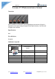
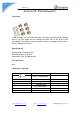
Connection diagram
Tips: P4, P5 and P6 is null.
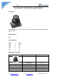
Potentiometer sensor
Up Pin -> 5V0
Mid Pin -> AINT0
Down Pin -> GND
PCF 8591
VCC -> 5V0
GND -> GND
SDA -> SDA1
SCL -> SCL1
Compile and Run
Tips: Refer to the operation demo (Step4 to Step7).
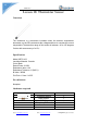
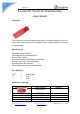
Application effect
Running the program, and rotating the Potentiometer that you will see the
analog value of Potentiometer .