Guide V1.0 Starter Kit for RPI Introduction WiringPi WiringPi is a PIN based GPIO access library written in C for the BCM2835 used in the Raspberry Pi. It’s released under the GNU LGPLv3 license and is usable from C, C++ and RTB (BASIC) as well as many other languages with suitable wrappers. It’s designed to be familiar to people who have used the Arduino “wiring” system.
Guide V1.0 Catalog Introduction ...................................................................................................... 1 Operation demo ............................................................................................... 3 Lesson 1: LED blink ......................................................................................... 8 Lesson 2: Button ............................................................................................ 11 Lesson 3: Ball switch ............
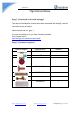
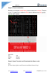
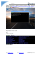
Guide V1.0 Operation demo Step 1: Download and install wiringpi Tips: Most of the Rapbian versions have been preloaded with wiringPi, and the test methods are as follows: Open terminal and run: gpio -v If you get something, then you have it already installed. If not, please refer it: http://wiringpi.com/download-and-install/ Step 2: Hardware required Material diagram Email: keen@elecrow.
Guide V1.0 Step 3: Circuit connection Because it is using the wiringPi library, the pins have been re-layout. The pins on the “T- Cobbler Plus” is basic for BCM which is different from wPi, please refer the “wPi” number. Connection: RPI GPIO17 GND LED Long pin Short pin Step 4: Open Terminal and Download the Demo code Run: git clone https://github.com/Elecrow-keen/Basic-Starter-Kit.git Email: keen@elecrow.com Web: www.elecrow.
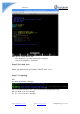
Guide V1.0 Tips: We will continue to update our resources on Github, please always pay attention the url: https://github.com/Elecrow-keen/Update-for-Basic-Starter-Kit Step 5: Enter Demo code Run: cd Basic-Starter-Kit cd Lesson1_LED-blink sudo nano blink.c Email: keen@elecrow.com Web: www.elecrow.
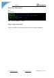
Guide V1.0 Tips: you can edit the Demo code. The compiling is: gcc -Wall -o blink blink.c -lwiringPi And run the program is: sudo ./blink Step 6: Exit and save When you want to exit ,you need to “Ctrl+O” and “Ctrl+X” Step 7: Compiling Run: gcc -Wall -o blink blink.c -lwiringPi Tips: if you want to compile “xxx.c” and you need run it by following this way. Run: gcc -Wall -o xxx xxx.c -lwiringPi Or: g++ -Wall -o xxx xxx.c -lwiringPi Email: keen@elecrow.com Web: www.elecrow.
Guide V1.0 Step 8: Run the program Run: sudo ./blink Tips: Exit the Program -> “Ctrl+c”. Step 9: Application effect Turns on an LED on for one second, then off for one second, repeatedly. Email: keen@elecrow.com Web: www.elecrow.
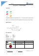
Guide V1.0 Lesson 1: LED blink Overview The LED is designed for the beginners of RPI. It is the best way to step into the from RPI what it’s I/O pins. The LED is the best choice to help you learn I/O pins. Specification Pin definition LED Long pin Short pin -> -> RPI GPIO17 GND Hardware required Material diagram Email: keen@elecrow.com Material name LED 220/330Ω resistor Raspberry Pi Board Web: www.elecrow.
Guide V1.0 T-Cobbler Plus 1 40P GPIO Cable 1 Breadboard 1 Jumper wires Several Breadboard schematic All the tie points (indicated in the picture) of the different colors are connected together. Email: keen@elecrow.com Web: www.elecrow.
Guide V1.0 Connection diagram Connection: RPI GPIO17 GND LED Long pin Short pin Compile and Run Tips: Refer to the operation demo (Step4 to Step7). Application effect Running the program, turns on an LED on for one second, then off for one second, repeatedly. Email: keen@elecrow.com Web: www.elecrow.
Guide V1.0 Lesson 2: Button Overview This lesson will teach you how to use button. Specification Size: 6 x 6 x 5mm Temperature: -30 ~ +70 Centigrade Pin definition It is the definition of Button pin: Hardware required Material diagram Email: keen@elecrow.com Material name Button Number 1 10KΩ resistor Raspberry Pi Board 1 1 Web: www.elecrow.
Guide V1.0 T-Cobbler Plus 1 40P GPIO Cable 1 Breadboard 1 Jumper wires Several Connection diagram Connection RPI GPIO17 3V3 Button 1 2 Compile and Run Tips: Refer to the operation demo (Step4 to Step7). Application effect Running the program ,and pressing the button, the screen will show the state of the button. Email: keen@elecrow.com Web: www.elecrow.
Guide V1.0 Lesson 3: Ball switch Overview This lesson will teach you how to use ball module, which is simple and easy to use. Specification Pin definition Pin non polarity. Hardware required Material diagram Email: keen@elecrow.com Material name Ball Switch 10KΩ resistor Raspberry Pi Board T-Cobbler Plus 40P GPIO Cable Breadboard Jumper wires Web: www.elecrow.
Guide V1.0 Connection diagram Connection RPI GPIO17 3v3 Ball Switch pin 1 pin 2 Compile and Run Tips: Refer to the operation demo (Step4 to Step7). Application effect Running the program ,and shocking the ball switch, the screen will show the state of the ball switch. Email: keen@elecrow.com Web: www.elecrow.
Guide V1.0 Lesson 4: Active buzzer Overview This is an active buzzer experiment. Active means that the direct power supply can make a sound. Specification Voltage: DC 5V Min Sound Output at 10cm: 85dB; Total Size (Pin Not Included): 12 x 9mm/0.47" x 0.35"(D*H) Pin definition Active Buzzer Long pin/+ -> Short pin -> RPI GPIO17 GND Hardware required Material diagram Email: keen@elecrow.
Guide V1.0 Connection diagram Connection Active Buzzer Long pin/+ -> Short pin -> RPI GPIO17 GND Compile and Run Tips: Refer to the operation demo (Step4 to Step7). Application effect Running the program, the buzzer will be ringing. Email: keen@elecrow.com Web: www.elecrow.
Guide V1.0 Lesson 5: Passive buzzer Overview This lesson will teach you how to use Passive buzzer, which is simple and easy to use. Specification Working Voltage: 3V/5V Resistance: 16Ohm Resonance Frequency: 2KHZ Pin definition Passive Buzzer Long pin/+ -> Short pin -> RPI GPIO17 GND Hardware required Material diagram Email: keen@elecrow.com Material name Passive buzzer Number 1 Raspberry Pi Board T-Cobbler Plus 40P GPIO Cable Breadboard Jumper wires 1 1 1 1 Several Web: www.elecrow.
Guide V1.0 Connection diagram Connection Passive Buzzer Long pin/+ -> Short pin -> RPI GPIO17 GND Compile and Run Tips: Refer to the operation demo (Step4 to Step7). Application effect Running the program, the buzzer will be ringing. Email: keen@elecrow.com Web: www.elecrow.
Guide V1.0 Lesson 6: Relay module Overview This lesson will teach you how to use Relay module, which is simple and easy to use. Specification Null Pin definition RPI GPIO17 5v0 GND Relay Module S + - Hardware required Material diagram Email: keen@elecrow.com Material name Relay Module Number 1 Raspberry Pi Board T-Cobbler Plus 40P GPIO Cable Breadboard Jumper wires 1 1 1 1 Several Web: www.elecrow.
Guide V1.0 Connection diagram Connection RPI GPIO17 5V0 GND Relay Module S + - Compile and Run Tips: Refer to the operation demo (Step4 to Step7). Application effect Running the program, according to the screen tips control relay. Email: keen@elecrow.com Web: www.elecrow.
Guide V1.0 Lesson 7: RGB LED Overview This lesson will teach you how to use a RGB (Red Green Blue) LED with an RPI, which is simple and easy to use. Specification RGB led: Emitting Light Color: Blue, Red, Green Size(Approx): 5 x 35mm/ 0.2" x 1.37" (D * L) Forward Voltage: 3.0-3.4V Luminous Intensity: 12000-14000mcd Pin definition RGB LED R GND G B -> -> -> -> RPI GPIO17 GND GPIO27 GPIO22 Hardware required Material diagram Email: keen@elecrow.
Guide V1.0 40P GPIO Cable Breadboard Jumper wires 1 1 Several Connection diagram Connection RGB LED R -> GND -> G -> B -> RPI GPIO17 GND GPIO27 GPIO22 Compile and Run Tips: Refer to the operation demo (Step4 to Step7). Application effect Running the program, you will see the LED loop emit 6 different colors of light. Email: keen@elecrow.com Web: www.elecrow.
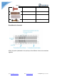
Guide V1.0 Lesson 8: 1 digit 7 Segment Displays Overview This experiment is similar to the LED experiment, the same is the control of LED, but the experiment can achieve time counting function. Specification Null Pin definition Hardware required Material diagram Material name 1 Digit 7 Segment displays 220/330Ω Raspberry Pi Board Email: keen@elecrow.com Web: www.elecrow.
Guide V1.0 T-Cobbler Plus 40P GPIO Cable Breadboard Jumper wires 1 1 1 Several Connection diagram Note: Pay attention to the direction of digital tube. Connection: RPI TXD0 RXD0 GPIO18 GPIO23 GPIO24 GPIO25 SPICSO SPICSI GND Email: keen@elecrow.com -> -> -> -> -> -> -> -> -> SEG P C D E G F A B COM Web: www.elecrow.
Guide V1.0 Compile and Run Tips: Refer to the operation demo (Step4 to Step7). Application effect You will see the number on the digital tube increased from 0 to 9. Lesson 9: 4 digit 7 Segment Displays Overview This experiment is similar to the LED experiment, the same is the control of LED, but the experiment can achieve time counting function. Specification Null Pin definition Hardware required Material diagram Email: keen@elecrow.com Material name Web: www.elecrow.
Guide V1.0 4 Digit 7 Segment displays 220/330Ω Raspberry Pi Board T-Cobbler Plus 40P GPIO Cable Breadboard Jumper wires 1 8 1 1 1 1 Several Connection diagram Note: Pay attention to the direction of digital tube. Connection: RPI TXD0 RXD0 GPIO18 GPIO23 GPIO24 GPIO25 SPICSO SPICSI Email: keen@elecrow.com -> -> -> -> -> -> -> -> SEG A4 g c DP d e A1 a Web: www.elecrow.
Guide V1.0 EECLK GPIO12 GPIO16 GPIO20 -> -> -> -> f A2 A3 b Compile and Run Tips: Refer to the operation demo (Step4 to Step7). Application effect Running the program, you will see the number of digital tube display increasingly. Lesson 10: Heart-shaped display experiment Overview This experiment using 8*8 dot matrix display a beating heart animation. Specification Please view 1588 ABxx.pdf. Path: \Datasheet\1588 ABxx.pdf Email: keen@elecrow.com Web: www.elecrow.
Guide V1.0 Pin definition Hardware required Material diagram Material name LED matrix 220/330Ω Raspberry Pi Board T-Cobbler Plus 40P GPIO Cable Breadboard Jumper wires Email: keen@elecrow.com Web: www.elecrow.
Guide V1.0 Connection diagram Connection: LED Matrix pin1 -> pin2 -> pin3 -> pin4 -> pin5 -> pin6 -> pin7 -> pin8 -> pin9 -> pin10 -> pin11 -> pin12 -> pin13 -> pin14 -> pin15 -> pin16 -> GPIO26 GPIO19 GPIO13 GPIO6 GPIO5 EEDATA SPISCLK SPIMISO GPIO25 SPICSO SPICSI EECLK GPIO12 GPIO16 GPIO20 GPIO21 Note: Part of the pin needs to be connected to a resistor. Compile and Run Tips: Refer to the operation demo (Step4 to Step7). Email: keen@elecrow.com Web: www.elecrow.
Guide V1.0 Application effect Please ensure that the connection correct, then run the program, you will see the heart beating animation. Lesson 11: 9G servo Overview This lesson will teach you how to use 9G servo. Sweeps the shaft of a RC servo motor back and forth across 180 degrees. Specification Please view SG90Servo-datasheet.pdf. Path: \Datasheet\ SG90Servo-datasheet.
Guide V1.0 Raspberry Pi Board T-Cobbler Plus 40P GPIO Cable Breadboard Jumper wires 1 1 1 1 Several Connection diagram Connection RPI GPIO18 5V0 GND Servo Motor Yellow Wire Red Wire Black Wire Compile and Run Tips: Refer to the operation demo (Step4 to Step7). Application effect Running the program, then you can control the Servo motor by the screen tips. Email: keen@elecrow.com Web: www.elecrow.
Guide V1.0 Lesson 12: Stepper Motor Overview This lesson will teach you how to use Stepper Motor. Specification Please view “Stepper-Motor.pdf” Path: \Datasheet\ Stepper-Motor.pdf Pin definition Hardware required Material diagram Email: keen@elecrow.com Material name Step motor Number 1 ULN2003 step motor driver board Raspberry Pi Board 1 Web: www.elecrow.
Guide V1.0 T-Cobbler Plus 1 40P GPIO Cable 1 Breadboard 1 Jumper wires Several Connection diagram Connection RPI GPIO17 GPIO18 GPIO27 GPIO22 “+” “-” Stepper Motor IN1 IN2 IN3 IN4 5V0 GND Compile and Run Tips: Refer to the operation demo (Step4 to Step7). Application effect Running the program, then you can control the relay by the screen tips. Email: keen@elecrow.com Web: www.elecrow.
Guide V1.0 Lesson 13: Ultrasonic ranging Overview This lesson will teach you how to use HC-SR04 module to test distance. It is generally used in the robot. Specification Please view “HCSR04.pdf” Path: \Datasheet\ HCSR04.pdf Pin definition HC SR04 Vcc Trig Echo Gnd -> -> -> -> RPI 5V0 GPIO23 GPIO24 GND Hardware required Material diagram Email: keen@elecrow.com Material name HCSR04 Number 1 Raspberry Pi Board T-Cobbler Plus 40P GPIO Cable Breadboard Jumper wires 1 1 1 1 Several Web: www.
Guide V1.0 Connection diagram Connection HC SR04 Vcc -> Trig -> Echo -> Gnd -> RPI 5V0 GPIO23 GPIO24 GND Compile and Run Tips: Refer to the operation demo (Step4 to Step7). Application effect Running the program, you will see the parameters returned by the ultrasonic module. Email: keen@elecrow.com Web: www.elecrow.
Guide V1.0 Lesson 14: Touch Lamp Overview This is a touch sensor to control the LED lamp experiment, it can control each LED light, but also can achieve the effect of breathing light. Specification Null Pin definition Touch sensor GND -> VCC -> SIG -> GND 5V data Hardware required Material diagram Material name Touch Sensor Number 1 RGB LED 1 3 220/330Ω Raspberry Pi Board T-Cobbler Plus 40P GPIO Cable Email: keen@elecrow.com Web: www.elecrow.
Guide V1.0 Breadboard Jumper wires 1 Several Connection diagram Touch sensor GND -> VCC -> SIG -> RGB LED R -> GND -> G -> B -> RPI GND 5V0 GPIO18 GPIO23 GND GPIO24 GPIO25 Compile and Run Tips: Refer to the operation demo (Step4 to Step7). Application effect Through the touch panel, you can control the LED light. Email: keen@elecrow.com Web: www.elecrow.
Guide V1.0 Lesson 15: PCF8591 Module Overview The PCF8591 module an 8-bit A/D Converter & D/A Converter PCF8591 with four analog inputs, one analog output and a serial I2C-bus interface. The PCF8591 module features I2C pinheader on one side, and I2C connector on the opposite side. Hence, it's more flexible to connect the board to your development system.
Guide V1.0 Connection diagram Tips: Select photosistence, so we need to use P5, P4 sand P6 is null. PCF 8591 VCC GND SDA SCL -> -> -> -> 5V0 GND SDA1 SCL1 Compile and Run Tips: Refer to the operation demo (Step4 to Step7). If print: Unable to open I2C device You need to open IIC. Enter Desktop: Preferences->Raspberry Pi Configuration->Interfaces->Enabled I2C->reboot. Application effect Running the program, you will see the analog value of photosistence sensor. Email: keen@elecrow.com Web: www.
Guide V1.0 Lesson 16: Flame Sensor Overview The flame sensor can be used to detect fire or other wavelength at 760 nm ~ 1100 nm light. In the fire-fighting robot game, the flame plays an important role in the probe, which can be used as the robot's eyes to find fire source or football. It can make use of fire-fighting robots, soccer robots. The flame sensor's operating temperature is -25 degrees Celsius to 85 degrees Celsius.
Guide V1.0 Connection diagram Tips: P4, P5 and P6 is null. Flame sensor Short Pin -> Long Pin -> 5V0 AINT0 PCF 8591 VCC GND SDA SCL 5V0 GND SDA1 SCL1 -> -> -> -> Compile and Run Tips: Refer to the operation demo (Step4 to Step7). Application effect Running the program, you will see the analog value of Flame sensor. Email: keen@elecrow.com Web: www.elecrow.
Guide V1.0 Lesson 17: Photoresistance Sensor Overview As the resistance of the sensor varies depending on the amount of light it is exposed to, the output voltage changes with the ligth intensity. It can be used to trigger other modules. Specification Null Pin definition Nonpolar. Hardware required Material diagram Email: keen@elecrow.
Guide V1.0 Connection diagram Tips: P4, P5 and P6 is null. Photoresistance sensor Pin1 -> Pin2 -> 5V0 AINT0 PCF 8591 VCC GND SDA SCL 5V0 GND SDA1 SCL1 -> -> -> -> Compile and Run Tips: Refer to the operation demo (Step4 to Step7). Application effect Running the program, you will see the analog value of Photoresistance sensor. Email: keen@elecrow.com Web: www.elecrow.
Guide V1.0 Lesson 18: Thermistor Sensor Overview The resistance of a thermistor increases when the ambient temperature decreases, so the RPI can detects the voltage and thus to caculate the current temperature.The detection range of this sensor is between -40 to 125 degrees Celsius with an accuracy of ±1.5℃. Specification Model: MF52-103 Insulation Material: Ceramic Color: Black Rated Power: 0.05W Resistance Value: 10k Resistance Tolerance: H (±3%) B Value: 3950K Pin Pitch: 1.5mm / 0.
Guide V1.0 Breadboard Jumper wires 1 Several Connection diagram Tips: P4, P5 and P6 is null. Photoresistance sensor Pin1 -> Pin2 -> 5V0 AINT0 PCF 8591 VCC GND SDA SCL 5V0 GND SDA1 SCL1 -> -> -> -> Compile and Run Tips: Refer to the operation demo (Step4 to Step7). Application effect Running the program, you will see the analog value of Thermistor sensor. Email: keen@elecrow.com Web: www.elecrow.
Guide V1.0 Lesson 19: Potentiometer Overview In this example, we use a potentiometer, we read its value using one analog input of an RPI board and we change the blink rate of the built-in LED accordingly. The resistor's analog value is read as a voltage because this is how the analog inputs work.
Guide V1.0 Connection diagram Tips: P4, P5 and P6 is null. Potentiometer sensor Up Pin -> Mid Pin -> Down Pin -> PCF 8591 VCC -> GND -> SDA -> SCL -> 5V0 AINT0 GND 5V0 GND SDA1 SCL1 Compile and Run Tips: Refer to the operation demo (Step4 to Step7). Application effect Running the program, and rotating the Potentiometer that you will see the analog value of Potentiometer . Email: keen@elecrow.com Web: www.elecrow.
Guide V1.0 Lesson 20: Water level monitoring experiment Overview This is a water level measurement experiment, it is relatively simple to achieve, only need to read the value of the analog port(A0 or others), and then converted to a percentage.
Guide V1.0 Breadboard Jumper wires 1 Several Connection diagram Tips: P4, P5 and P6 is null. Water sensor + S PCF 8591 VCC GND SDA SCL -> -> -> GND 5V0 AINT0 -> -> -> -> 5V0 GND SDA1 SCL1 Compile and Run Tips: Refer to the operation demo (Step4 to Step7). Application effect Running the program, put the water level sensor enter water and you will see the analog value of water sensor. Email: keen@elecrow.com Web: www.elecrow.
Guide V1.0 Lesson 21: Joystick experiment Overview This experiment is to learn how to use the joystick of the analog output and digital output. Specification Null. Pin definition GND +5V VRx VRy SW -> -> -> -> -> GND VCC I/O I/O I/O Hardware required Material diagram Email: keen@elecrow.com Material name Joystick Module Number 1 PCF8591 Raspberry Pi Board T-Cobbler Plus 40P GPIO Cable Breadboard Jumper wires 1 1 1 1 1 Several Web: www.elecrow.
Guide V1.0 Connection diagram Tips: P4, P5 and P6 is null. Joystick Module GND +5V VRX VRY SW -> -> -> -> -> GND 5V0 AINT2 AINT1 AINT0 PCF 8591 VCC GND SDA SCL -> -> -> -> 5V0 GND SDA1 SCL1 Compile and Run Tips: Refer to the operation demo (Step4 to Step7). Application effect By rotating or pressing the joystick, you will see the change in value. Email: keen@elecrow.com Web: www.elecrow.
Guide V1.0 Lesson 22: IR remote control experiment Overview In this lesson, we use the lirc library to read infrared signals returned by buttons of the remote control and translate them to button values. When a button is pressed, the IR transmitter in the remote control will send out the corresponding IR encoding signals. On the other side, when the IR receiver receives certain encoding signals, it will decode them to identify which button is pressed.
Guide V1.0 40P GPIO Cable Breadboard Jumper wires 1 1 Several Connection diagram Note: Please view Pin definition. Connection RPI GPIO21 GND 5V0 IR Receiver -> OUT -> GND -> VCC Compile and Run Open terminal and install the LIB of lirc, run: git clone https://github.com/Elecrow-keen/Elecrow-lirc-setup.git cd Elecrow-lirc-setup sudo ./setup And next, open the lesson of IR-Remote, compile and run. Tips: Email: keen@elecrow.com Web: www.elecrow.
Guide V1.0 Compiling: gcc -Wall -o remote remote.c -lwiringPi -llirc_client Application effect Running the program, press the button of the remote control, you will see that each button will have the corresponding coding. Lesson 23: IR remote control LED Overview In this lesson, we use the Remote to control a LED. Specification IR Receiver: Please view “IR Receiver-datasheet.pdf” Path: \ Datasheet\ IR Receiver-datasheet.pdf Pin definition Hardware required Material diagram Email: keen@elecrow.
Guide V1.0 IR Remote IR Receiver LED 220/330Ω resistor Raspberry Pi board T-Cobbler Plus 40P GPIO Cable Breadboard Jumper wires 1 1 1 1 1 1 1 1 Several Connection diagram Note: Please view Pin definition. Connection RPI GPIO21 GND 5V0 IR Receiver -> OUT -> GND -> VCC Email: keen@elecrow.com Web: www.elecrow.
Guide V1.0 Compile and Run (Tips: If you have already added, skip this step) Open terminal and install the LIB of lirc, run: git clone https://github.com/Elecrow-keen/Elecrow-lirc-setup.git cd Elecrow-lirc-setup sudo ./setup And next, open the lesson of IR-Remote, compile and run. Application effect Running the program, press the button “CH-” or “CH+”, you will see the LED Open or Close.
Guide V1.0 Hardware required Material diagram Material name DHT11 Module Raspberry Pi Board T-Cobbler Plus 40P GPIO Cable Breadboard Jumper wires Number 1 1 1 1 1 Several Connection diagram Connection RPI GND GPIO4 5V0 DHT11 GND/’-’ DATA/’out’ VCC/’+’ Compile and Run Tips: Refer to the operation demo (Step4 to Step7). Application effect Running the program, you will see the parameters returned by the DHT11 module. Email: keen@elecrow.com Web: www.elecrow.
Guide V1.0 Lesson 25: LCD1602 with IIC Overview This is an experiment on how to use LCD1602 with IIC, the next lesson will do a temperature and humidity monitoring experiment. Specification Please view LCD1602-datasheet.pdf. Path: \Datasheet\LCD1602-datasheet.pdf Pin definition LCD1602 GND VCC SDA SCL -> -> -> -> RPI GND 5V0 SDA1 SCL1 Hardware required Material diagram Material name LCD1602 with IIC Raspberry Pi Board T-Cobbler Plus 40P GPIO Cable Breadboard Jumper wires Email: keen@elecrow.
Guide V1.0 Connection diagram Connection LCD1602 GND VCC SDA SCL -> -> -> -> RPI GND 5V0 SDA1 SCL1 Compile and Run Tips: Refer to the operation demo (Step4 to Step7). If print: Unable to open I2C device You need to open IIC. Enter Desktop: Preferences->Raspberry Pi Configuration->Interfaces->Enabled I2C->reboot. Application effect Running the program, LCD display string. If the LCD display is abnormal, please check the lines or adjust the potentiometer. Email: keen@elecrow.com Web: www.elecrow.
Guide V1.0 Lesson 26: Temperature and humidity monitoring experiment Overview This is a more complex experiment, it can realize the monitoring of indoor temperature and humidity, and in the LCD above display value. Specification Please view LCD1602-datasheet.pdf、DHT11-datasheet.pdf and PCF8574.pdf.
Guide V1.0 T-Cobbler Plus 40P GPIO Cable Breadboard Jumper wires 1 1 1 Several Connection diagram Connection RPI GND -> GPIO4 -> 5V0 -> DHT11 GND/’-’ DATA/’out’ VCC/’+’ RPI GND 5V0 SDA1 SCL1 LCD1602 GND VCC SDA SCL -> -> -> -> Compile and Run Tips: Refer to the operation demo (Step4 to Step7). If print: Unable to open I2C device You need to open IIC. Enter Desktop: Preferences->Raspberry Pi Configuration->Interfaces->Enabled I2C->reboot.
Guide V1.0 the LCD. Email: keen@elecrow.com Web: www.elecrow.