SIM800C_Hardware_Design_V1.
Smart Machine Smart Decision Document Title SIM800C Hardware Design Version V1.02 Date 2015-04-27 Status Release Document Control ID SIM800C_Hardware_Design_V1.02 General Notes SIMCom offers this information as a service to its customers, to support application and engineering efforts that use the products designed by SIMCom. The information provided is based upon requirements specifically provided to SIMCom by the customers.
Smart Machine Smart Decision Contents Version History............................................................................................................ 8 1. Introduction.......................................................................................................... 9 2. SIM800C Overview ............................................................................................. 9 2.1. 2.2. 2.3. 2.4. 3. Package Information ..........................................................
Smart Machine Smart Decision 4.8.2. 4.8.3. SIM Card Design Guide...................................................................................................................... 32 Design Considerations for SIM Card Holder ...................................................................................... 32 4.9. ADC ....................................................................................................................................34 4.10. Network Status Indication................
Smart Machine Smart Decision III. IV. Terms and Abbreviations ....................................................................................................49 Safety Caution.....................................................................................................................51 SIM800C_Hardware_Design_V1.
Smart Machine Smart Decision Table Index TABLE 1: MODULE INFORMATION ............................................................................................................................. 9 TABLE 2: SIM800C KEY FEATURES ............................................................................................................................. 9 TABLE 3: CODING SCHEMES AND MAXIMUM NET DATA RATES OVER AIR INTERFACE ............................ 11 TABLE 4: OVERVIEW OF OPERATING MODES..................
Smart Machine Smart Decision Figure Index FIGURE 1: SIM800C FUNCTIONAL DIAGRAM......................................................................................................... 12 FIGURE 2: PIN OUT DIAGRAM (TOP VIEW) ............................................................................................................. 13 FIGURE 3: DIMENSIONS OF SIM800C (UNIT: MM) .................................................................................................
Smart Machine Smart Decision Version History Date Version Description of change Author 2014-11-06 1.00 Origin Yanwu.wang; Xiaobo.bai 2015-01-06 1.01 Update figure1,figure12,figure40 Delete figure26 Add VRTC segment to table5 Update table11,table34,table35,table36 Yanwu.wang; Xiaobo.bai 2015-04-27 1.02 Update figure7,figure10,figure11,figure10,figure12,figure13, figure14,figure23,figure37,figure38 Update table1,table2 Yanwu.wang; Xiaobo.bai SIM800C_Hardware_Design_V1.
Smart Machine Smart Decision 1. Introduction This document describes SIM800C hardware interface in great detail. The document can help customer to quickly understand SIM800C interface specifications, electrical and mechanical details. With the help of this document and other SIM800C application notes, customer guide, customers can use SIM800C to design various applications quickly. 2.
Smart Machine Smart Decision search the 4 frequency bands automatically. The frequency bands can also be set by AT command “AT+CBAND”. For details, please refer to document [1].
Smart Machine Smart Decision Table 3: Coding schemes and maximum net data rates over air interface Coding scheme 1 timeslot 2 timeslot 4 timeslot CS-1 9.05kbps 18.1kbps 36.2kbps CS-2 13.4kbps 26.8kbps 53.6kbps CS-3 15.6kbps 31.2kbps 62.4kbps CS-4 21.4kbps 42.8kbps 85.6kbps 2.3. Operating Mode The table below summarizes the various operating modes of SIM800C.
Smart Machine Smart Decision 2.4. Functional Diagram The following figure shows a functional diagram of SIM800C: GSM baseband GSM RF Antenna interface Other interface P ow er S upply P ow er m anagem ent unit G SM Radio Frequency BT R TC D igitalInterface A nalog Interface UART Audio A nalog base band AD C D igitalbase band S IM U SB G P IO Figure 1: SIM800C functional diagram SIM800C_Hardware_Design_V1.
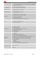
Smart Machine Smart Decision 3. Package Information 3.1. Pin Out Diagram Figure 2: Pin out Diagram (Top view) 3.2. Pin Description Table 5: Pin description Pin name Pin number I/O Description 34,35 I Power supply Comment Power supply VBAT SIM800C_Hardware_Design_V1.
Smart Machine Smart Decision VRTC 28 I/O Power supply for RTC It is recommended to connect with a battery or a capacitor (e.g. 4.7uF). VDD_EXT 40 O 2.8V power output If these pins are unused, keep open. GND 8,13,19,21,27,30, 31,33,36,37 Ground GND for VBAT recommend to use 36,37pin 39 I PWRKEY should be pulled low at least 1 second and then released to power on/down the module. Internally VBAT.
Smart Machine Smart Decision keep open. Antenna interface GSM_ANT 32 I/O Connect GSM antenna BT_ANT 20 I/O Connect Bluetooth antenna O Synchronizing signal of RF Synchronizing signal of RF RF_SYNC 29 3.3. Package Dimensions Figure 3: Dimensions of SIM800C (Unit: mm) SIM800C_Hardware_Design_V1.
Smart Machine Smart Decision Figure 4: Recommended PCB footprint outline (Unit: mm) SIM800C_Hardware_Design_V1.
Smart Machine Smart Decision 4. Application Interface 4.1. Power Supply The power supply range of SIM800C is from 3.4V to 4.4V. Recommended voltage is 4.0V. The transmitting burst will cause voltage drop and the power supply must be able to provide sufficient current up to 2A. For the VBAT input, a bypass capacitor (low ESR) such as a 100 µF is strongly recommended. For the VBAT input, a 100uF Tantalum capacitor (CA low ESR) and a 1uF~10uF Ceramics capacitor CB are strongly recommended.
Smart Machine Smart Decision following figure is the reference circuit. + C 102 C 101 100uF 1uF 5 O n/O ff P W R _C T R L GND U 101 LM 2596-A D J 1 2 V in V out D C input FB 4 L101 C 103 VBAT 270Ω 100uH D 102 330uF M B R 360 3 F B 101 + C 104 100nF R 101 2.2K R 102 1K Figure 7: Reference circuit of the DC-DC power supply The single 3.7V Li-ion cell battery can be connected to SIM800C VBAT pins directly.
Smart Machine Smart Decision 4.1.2. Monitoring Power Supply AT command “AT+CBC” can be used to monitor the VBAT voltage. For detail, please refer to document [1]. 4.2. Power on/off SIM800C 4.2.1. Power on SIM800C Customer can power on SIM800C by pulling down the PWRKEY pin for at least 1 second and release. This pin is already pulled up to VBAT in the module internal, so external pull up is not necessary. Reference circuits are shown as below. 3V 100K P ow er on/off logic PW R KEY 1K 4.
Smart Machine Smart Decision When power on procedure is completed, SIM800C will send following URC to indicate that the module is ready to operate at fixed baud rate. RDY This URC does not appear when autobauding function is active. Note: Customer can use AT command “AT+IPR=x” to set a fixed baud rate and save the configuration to non-volatile flash memory. After the configuration is saved as fixed baud rate, the Code “RDY” should be received from the serial port every time when SIM800C is powered on.
Smart Machine Smart Decision SIM800C can be powered off by AT command “AT+CPOWD=1”. This procedure makes the module log off from the network and allows the software to enter into a secure state to save data before completely shut down. Before the completion of the power off procedure, the module will send URC: NORMAL POWER OFF At this moment, AT commands can not be executed any more. Power off mode can also be indicated by STATUS pin, which is at low level at this time.
Smart Machine Smart Decision 3) Power on the module. T 3 >800m s 1s“can be used to set SIM800C into minimum functionality. When SIM800C is in sleep mode and minimum functionality mode, the current of module is lowest. 4.3.1.
Smart Machine Smart Decision 4.3.3. Wake Up SIM800C from Sleep Mode 1 When SIM800C is in sleep mode 1(AT+CSCLK=1), the following methods can wake up the module: Pull down DTR pin. The serial port will be active after DTR pin is pulled to low level for about 50ms. Receive a voice or data call from network. Receive a SMS from network. Receive external interrupt. Note: After module has received incoming call or new SMS, serial port can report URC, but the serial port can not input AT command.
Smart Machine Smart Decision M odule V R TC 1.5K R TC C ore N on-chargeable B ackup B attery Figure 16: RTC supply from non-chargeable battery Rechargeable battery backup M odule V R TC 1.5K R echargeable B ackup B attery R TC C ore Figure 17: RTC supply from rechargeable battery Note: When shut off VBAT and power on VRTC only, the clock error becomes larger. 4.5. Serial Port and USB Interface SIM800C default provides one unbalanced asynchronous serial ports.
Smart Machine Smart Decision control. AT command “AT+IFC=0,0”can disable hardware flow control. For more details please refer to document [1]. Table 9: Serial port characteristics Symbol Min Max Unit VIL -0.3 0.7 V VIH 2.1 3.1 V VOL - 0.4 V VOH 2.4 - V 4.5.1 Function of Serial Port Serial port: Full mode device. Contain data lines UART1_TXD/UART1_RXD, hardware flow control lines UART1_RTS/UART1_CTS, status lines UART1_DTR、UART1_DCD and UART1_RI.
Smart Machine Smart Decision M odule(D C E ) S erialP ort C ustom er(D T E ) S erialP ort U A R T1_T X D TX D U A R T1_R X D RXD U A R T1_R T S R TS U A R T1_C T S C TS U A R T1_D T R D TR U A R T1_D C D DCD U A R T1_R I R IN G GND GND Figure 18: Connection of the serial interfaces If the voltage of UART is 3.3V, the following reference circuits are recommended. If the voltage is 3.0V, please change the resistors in the following figure from 5.6K to 14K.
Smart Machine Smart Decision V D D _E X T M odule D TE VDD 4.7K V D D _E X T 4.7K 47K RXD U A R T 1_T X D Figure 21: TX level matching circuit V D D _E X T M odule D TE V D D _E X T VD D 4.7K 4.7K 47K TX D U A R T 1_R X D Figure 22: RX level matching circuit 4.5.3 Debug Interface SIM800C could achieve software debug function through USB interface.
Smart Machine Smart Decision Pin Min Typ Max Unit USB_VBUS 4.3 5.0 7.0 V 4.5.4 Software Upgrade Customer could upgrade module’s firmware through USB or UART interface. If upgrading through USB interface, it is necessary to power on SIM800C first, and then connect USB_VBUS, USB_DP, USB_DN, and GND to PC. There is no need to operate PWRKEY pin in the whole procedure, when SIM800C detects USB_VBUS and could communicate normally with USB_DP and USB_DN, it will enter USB download mode automatically.
Smart Machine Smart Decision RI H IG H E stablish the call H ang up the call LO W Idle R ing Figure 25: UART1_RI behaviour of voice calling as a receiver H IG H RI 120m s LO W Idle R eceive S M S URC Figure 26: UART1_RI behaviour of URC or receive SMS However, if the module is used as caller, the UART1_RI will remain high. Please refer to the following figure. H IG H RI LO W R ing Idle E stablish the call H ang up the call Idle Figure 27: UART1_RI behaviour as a caller 4.7.
Smart Machine Smart Decision In order to improve audio performance, the following reference circuits are recommended. The audio signals have to be layout according to differential signal layout rules as shown in following figures. 4.7.1. Speaker Interfaces Configuration C lose to speaker 10pF 33pF 10pF 33pF 10pF 33pF 10pF 33pF 10pF 33pF 10pF 33pF ESD SPKP SPKN M odule ESD Figure 28: Speaker reference circuit 4.7.2.
Smart Machine Smart Decision Input level:0dBm0 - 69 - dB Table 14: Audio output characteristics Parameter Conditions Min Typ Max Unit Normal output RL=32 Ω receiver - 15 90 mW 4.7.4. TDD Audio signal could be interferenced by RF signal. Coupling noise could be filtered by adding 33pF and 10pF capacitor to audio lines. 33pF capacitor could eliminate noise from GSM850/EGSM900MHz, while 10pF capacitor could eliminate noise from DCS1800/PCS1900Mhz frequency.
Smart Machine Smart Decision V D D _E X T M odule 4.7K M O LE X -91228 S IM _V D D S IM _R S T S IM _C LK S IM _D E T 51Ω 51Ω S IM _D A T A 51Ω GND VC C VPP R ST C LK I/O PR ESEN C E G N D S IM C ard 100nF 22pF E S D A 6V 1 Figure 30: Reference circuit of the 8-pin SIM card holder The SIM_DET pin is used for detection of the SIM card hot plug in. Customer can select the 8-pin SIM card holder to implement SIM card detection function.
Smart Machine Smart Decision Figure 32: Molex 91228 SIM card holder Table 16: Pin description (Molex SIM card holder) Pin name Signal Description C1 SIM_VDD SIM card power supply C2 SIM_RST SIM card reset C3 SIM_CLK SIM card clock C4 GND Connect to GND C5 GND Connect to GND C6 VPP Not connect C7 SIM_DATA SIM card data I/O C8 SIM_DET Detect SIM card presence For 6-pin SIM card holder, SIMCom recommends to use Amphenol C707 10M006 512 .Customer can visit http://www.amphenol.
Smart Machine Smart Decision Figure 33: Amphenol C707 10M006 512 SIM card holder Table 17: Pin description (Amphenol SIM card holder) Pin name Signal Description C1 SIM_VDD SIM card power supply C2 SIM_RST SIM card reset C3 SIM_CLK SIM card clock C5 GND Connect to GND C6 VPP Not connect C7 SIM_DATA SIM card data I/O Note: Every time plug SIM card interval advice is greater than 2s. Otherwise may not be able to correct detection. 4.9.
Smart Machine Smart Decision Table 19: ADC specification Parameter Min Typ Max Unit Voltage range 0 - 2.8 V ADC Resolution - 10 - bits Sampling rate - - 1.0833 MHz 10 30 mV ADC precision 4.10. Network Status Indication Table 20: Pin definition of the NETLIGHT Pin name Pin number Description NETLIGHT 41 Network Status Indication The NETLIGHT pin can be used to drive a network status indication LED.
Smart Machine Smart Decision 4.11. Operating Status Indication The pin42 is for operating status indication of the module. The pin output is high when module is powered on, and output is low when module is powered off. Table 23: Pin definition of the STATUS Pin name Pin number Description STATUS 42 Operating status indication Note: For timing about STATUS, please reference to the chapter “4.2 power on/down scenarios” 4.11.1.
Smart Machine Smart Decision Pin name Pin number Mode 0(default) Mode 1 RF_SYNC 29 RF Synchronization Signal JD(RF jamming detection) Note: About AT+SJDR, please refer to document [1]. 4.13. Antenna Interface There are two antenna interfaces, GSM_ANT and BT_ANT. The input impendence of the antenna should be 50Ω, and the VSWR should be less than 2. It is recommended that the GSM antenna and the BT antenna should be placed as far as possible.
Smart Machine Smart Decision Normally R101 is 0Ω, C101 and C102 are not mounted. 4.13.2 Bluetooth Antenna Interface It is recommended to reserve the matching circuit as following: G ND (P in19) M odule BT A ntenna R 201 B T _A N T (P in20) C 201 C 202 GND (P in21) Figure 38: Bluetooth antenna matching circuit R201, C201, C202 are the matching circuit, the value should be defined by the antenna design. Normally R201 is 0R, C202 and C201 are not mounted.
Smart Machine Smart Decision 5. PCB Layout This section will give some guidelines on PCB layout, in order to eliminate interfere or noise. 5.1 Pin Assignment Before PCB layout, we should learn about pin assignment in order to get reasonable layout with so many external components. Following figure is the overview of pin assignment of the module.
Smart Machine Smart Decision 5.2.1 Antenna Interface 5.2.2 Power Supply 5.2.3 SIM card holder has no anti-EMI component inside.
Smart Machine Smart Decision 6. Electrical, Reliability and Radio Characteristics 6.1 Absolute Maximum Ratings The absolute maximum ratings stated in following table are stress ratings under non-operating conditions. Stresses beyond any of these limits will cause permanent damage to SIM800C. Table 27: Absolute maximum ratings Symbol Min Typ Max Unit VBAT - - 4.5 V Current 0 - 2.
Smart Machine Smart Decision VIH High-level input voltage VIL Low-level input voltage VOH High-level output voltage VOL Low-level output voltage 6.5 1.4 - - V 2.4 - - V - - 0.27 V 0.4 V 1.62 - - V 2.7 - - V - - 0.36 V - - 0.4 V Parameter Min Typ Max Unit Output voltage - 3.0 - - 1.8 - - - 10 mA SIM_VDD Characteristics Table 31: SIM_VDD characteristics Symbol VO IO 6.
Smart Machine Smart Decision @ f>200kHzss IVBAT Average currnet IMAX Peak current 2.0 mV 150 uA Power off mode 130 Sleep mode (AT+CFUN=1): ( BS-PA-MFRMS=9 ) ( BS-PA-MFRMS=5) ( BS-PA-MFRMS=2) 0.88 1 1.5 mA mA mA Idle mode (AT+CFUN=1): GSM850 EGSM900 DCS1800 PCS1900 13.8 13.8 13.8 13.
Smart Machine Smart Decision GND ±6KV ±12KV UART1_TXD /UART1_RXD ±4KV ±8KV Antenna port ±5KV ±10KV SPKP/SPKN/MICP/MICN ±4KV ±8KV PWRKEY ±4KV ±8KV 6.10 Radio Characteristics 6.10.1 Module RF Output Power The following table shows the module conducted output power, it is followed by the 3GPP TS 05.05 technical specification requirement.
Smart Machine Smart Decision 4 22 ±3 ±4 5 20 ±3 ±4 6 18 ±3 ±4 7 16 ±3 ±4 8 14 ±3 ±4 9 12 ±4 ±5 10 10 ±4 ±5 11 8 ±4 ±5 12 6 ±4 ±5 13 4 ±4 ±5 14 2 ±5 ±6 15 0 ±5 ±6 6.10.2 Module RF Receive Sensitivity The following table shows the module’s conducted receiving sensitivity, it is tested under static condition.
Smart Machine Smart Decision 7. Manufacturing 7.1. Top and Bottom View of SIM800C Figure 40: Top and bottom view of SIM800C 7.2. Typical Solder Reflow Profile Figure 41: Typical solder reflow profile of lead-free processes SIM800C_Hardware_Design_V1.
Smart Machine Smart Decision 7.3. The Moisture Sensitivity Level The moisture sensitivity level of SIM800C module is 3. The modules should be mounted within 168 hours after unpacking in the environmental conditions of temperature <30℃ and relative humidity of <60% (RH).
Smart Machine Smart Decision 8. Appendix I. Related Documents Table 42: Related documents SN Document name [1] SIM800 Series AT Command Manual [2] SIM800 Series UART Port Application Note_V1 02.doc [3] ITU-T Draft new recommendation V.25ter: Serial asynchronous automatic dialing and control [4] GSM 07.07: Digital cellular telecommunications (Phase 2+); AT command set for GSM Mobile Equipment (ME) [5] GSM 07.10: Support GSM 07.10 multiplexing protocol GSM 07.
Smart Machine Smart Decision II.
Smart Machine Smart Decision PBCCH Packet Broadcast Control Channel PCB Printed Circuit Board PCL Power Control Level PCS Personal Communication System, also referred to as GSM 1900 PDU Protocol Data Unit PPP Point-to-point protocol RF Radio Frequency RMS Root Mean Square (value) RX Receive Direction SIM Subscriber Identification Module SMS Short Message Service TE Terminal Equipment, also referred to as DTE TX Transmit Direction SINAD Signal to Noise and Distortion Ratio UART
Smart Machine Smart Decision IV. Safety Caution Table 45: Safety caution Marks Requirements When in a hospital or other health care facility, observe the restrictions about the use of mobiles. Switch the cellular terminal or mobile off, medical equipment may be sensitive to not operate normally for RF energy interference. Switch off the cellular terminal or mobile before boarding an aircraft. Make sure it is switched off.
Smart Machine Smart Decision Contact us: Shanghai SIMCom Wireless Solutions Co.,Ltd. Address: Building A, SIM Technology Building, No. 633, Jinzhong Road, Shanghai, P. R. China 200335 Tel: +86 21 3252 3300 Fax: +86 21 3252 3020 URL: www.sim.com/wm SIM800C_Hardware_Design_V1.