
Data Sheet

© Copyright 2012 WIZnet Co., Inc. All rights reserved.
8
iEthernet W5200
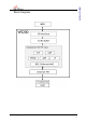
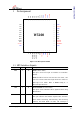
1 Pin Assignment
Figure 1 Pin Description W5200
1.1 MCU Interface Signals
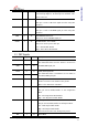
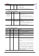
Symbol Type Pin No Description
nRST I 46 RESET ( Active LOW )
This pin is active Low input to initialize or re-initialize
W5200.
RESET should be held at least 2us after low assert, and
wait for at least 150ms after high de-assert in order for
PLL logic to be stable. Refer to RESET timing of “7
Electrical Specification”
nSCS I 41 SPI SLAVE SELECT ( Active LOW )
This pin is used to SPI Slave Select signal Pin when using
SPI interface.
nINT O 40 INTERRUPT (Active LOW )
This pin indicates that W5200 requires MCU attention
after socket connecting, disconnecting, data receiving
timeout, and WOL (Wake on LAN)
. The interrupt is
RSV
RSV
RSV
RSV
RSV
SPD
DUP
GNDA
VCC3V3A
GNDA
RXIN
RXIP
RSV
RSV
RSV
nINT
nSCS
SCLK
MOSI
MISO
PWDN
nRST
VCC3V3
GND
XI
XO
nFDXLED/M2
nSPDLED/M1
nLINKLED/M0
M3
RSV
VCC1V8
GND
GND
VCC3V3A
BIAS
37
38
39
40
41
42
43
44
45
46
47
48
22
21
20
19
18
17
16
15
14
13
29
28
27
26
25
24
23
1
2
3
4
5
6
7
8
9
10
11
12
W5200
34
33
32
31
30
36
35
GNDA
TXON
TXOP
XTALVDD
VCC3V3A
POWEROUT
GNDA
ANE
GND
VCC3V3
GND
VCC1V8