
Data Sheet


© Copyright 2012 WIZnet Co., Inc. All rights reserved.
72
iEthernet W5200
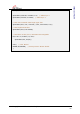
6.3 Process of using general SPI Master device
1. Configure Input/Output direction on SPI Master Device pins.
2. Configure nSCS as ‘High’ on inactive
3. Write target address for transmission on SPDR register (SPI Data Register).
4. Write OP code and data length for transmission on SPDR register.
5. Write desired data for transmission on SPDR register.
6. Configure nSCS as ‘Low’ (data transfer start)
7. Wait for reception complete
8. If all data transmission ends, configure nSCS as ‘High’
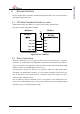
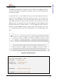
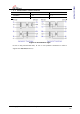
Figure 19 W5200 SPI Frame Format
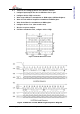
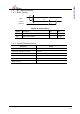
Figure 20 Address and OP/DATA Length Sequence Diagram