
Data Sheet

© Copyright 2012 WIZnet Co., Inc. All rights reserved.
12
iEthernet W5200
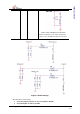
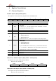
3. If ground plane width is adequate, having a separate analog ground plane and
digital ground plane is good practice.
4. If ground plane is not wide, design analog and digital ground planes as a single
ground plane, rather than separate them.
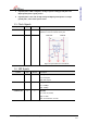
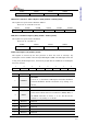
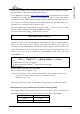
1.5 Clock Signals
Symbol Type Pin No Description
XI I 1 25MHz crystal input/output. A 25MHz crystal and
Oscillator is used to connect these pins.
Figure 4 Crystal Reference Schematic
XO O 2
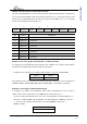
1.6 LED Signals
Symbol Type Pin No Description
nFDXLED/M2 O 3 Full Duplex/Collision LED
Low: Full-duplex
High: Half-duplex.
nSPDLED/M1 O 4 Link speed LED
Low: 100Mbps
High: 10Mbps
nLINKLED/M0 O 5 Link LED
Low: Link (10/100M)
High: Un-Link
blink: TX or RX state on Link
_
XTAL OUT
XTAL IN