
Data Sheet

© Copyright 2012 WIZnet Co., Inc. All rights reserved.
10
iEthernet W5200
This pin selects 100M/10M Speed Mode.
Low = 10M Speed Mode
High = 100M Speed Mode
This function activates only during reset period.
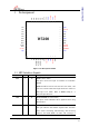
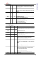
1.3 Miscellaneous Signals
Symbol Type Pin No Description
nFDXLED/M2
nSPDLED/M1
nLINKLED/M0
I 3,
4,
5
W5200 MODE SELECT
Normal mode : 111
Other test modes are internal test mode.
This function activates only during reset
period
M3 I 6 This pin should be pull-up.
RSV - 7,32,33,34,35,36,
37,38,39
Reserved Pin
The pin number 7 should be pull-up.
The reserved pins except the pin number 7
should be pull-down or GND.
Notes: Pull-Up/Down registor = 40KΩ to 100KΩ. Typical value are 75KΩ.
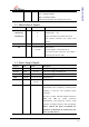
1.4 Power Supply Signals
Symbol Type Pin No Description
VCC3V3A Power 11, 15, 23 3.3V power supply for Analog part
VCC3V3 Power 27, 47 3.3V power supply for Digital part
VCC1V8 Power 8, 25 1.8V power supply for Digital part
GNDA Ground 13, 19, 22, 24 Analog ground
GND Ground 9, 10, 26,
28, 48
Digital ground
1V8O O 14 1.8V regulator output voltage
1.8V/200mA power created by internal power
regulator, is used for
core operation power
( VCC1V8).
Be sure to connect tantalum capacitor between
1V8O and GND for output frequency
compensation, and selectively connect 0.1uF
capacitor for high frequency noise decoupling.
Notice: 1V8O is the power for W520
0 core
operation. It should not be connected to the
power of other devices.