
Data Sheet


CC1101
SWRS061B Page 81 of 93
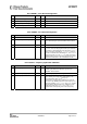
0x21: FREND1 – Front End RX Configuration
Bit Field Name Reset R/W Description
7:6 LNA_CURRENT[1:0] 1 (01) R/W Adjusts front-end LNA PTAT current output
5:4 LNA2MIX_CURRENT[1:0] 1 (01) R/W Adjusts front-end PTAT outputs
3:2 LODIV_BUF_CURRENT_RX[1:0] 1 (01) R/W Adjusts current in RX LO buffer (LO input to mixer)
1:0 MIX_CURRENT[1:0] 2 (10) R/W Adjusts current in mixer
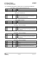
0x22: FREND0 – Front End TX Configuration
Bit Field Name Reset R/W Description
7:6 Reserved R0
5:4 LODIV_BUF_CURRENT_TX[1:0] 1 (0x01) R/W Adjusts current TX LO buffer (input to PA). The value to
use in this field is given by the SmartRF
®
Studio software
[7].
3 Reserved R0
2:0 PA_POWER[2:0] 0 (0x00) R/W Selects PA power setting. This value is an index to the
PATABLE, which can be programmed with up to 8 different
PA settings. In OOK/ASK mode, this selects the PATABLE
index to use when transmitting a ‘1’. PATABLE
index zero
is used in OOK/ASK when transmitting a ‘0’. The PATABLE
settings from index ‘0’ to the PA_POWER value are used for
ASK TX shaping, and for power ramp-up/ramp-down at the
start/end of transmission in all TX modulation formats.
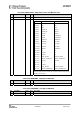
0x23: FSCAL3 – Frequency Synthesizer Calibration
Bit Field Name Reset R/W Description
7:6 FSCAL3[7:6] 2 (0x02) R/W Frequency synthesizer calibration configuration. The value
to write in this field before calibration is given by the
SmartRF
®
Studio software.
5:4 CHP_CURR_CAL_EN[1:0] 2 (0x02) R/W Enable charge pump calibration stage when 1
3:0 FSCAL3[3:0] 9 (1001) R/W Frequency synthesizer calibration result register. Digital bit
vector defining the charge pump output current, on an
exponential scale: IOUT =
I
0
·2
FSCAL3[3:0]/4
Fast frequency hopping without calibration for each hop
can be done by calibrating upfront for each frequency and
saving the resulting FSCAL3, FSCAL2 and FSCAL1 register
values. Between each frequency hop, calibration can be
replaced by writing the FSCAL3, FSCAL2 and FSCAL1
register values corresponding to the next RF frequency.