
Data Sheet


CC1101
SWRS061B Page 79 of 93
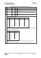
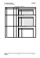
0x1D: AGCCTRL0 – AGC Control
Bit Field Name Reset R/W Description
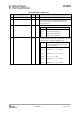
7:6 HYST_LEVEL[1:0] 2 (10) R/W Sets the level of hysteresis on the magnitude deviation (internal AGC
signal that determine gain changes).
Setting Description
0 (00) No hysteresis, small symmetric dead zone, high gain
1 (01)
Low hysteresis, small asymmetric dead zone, medium
gain
2 (10)
Medium hysteresis, medium asymmetric dead zone,
medium gain
3 (11)
Large hysteresis, large asymmetric dead zone, low
gain
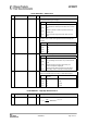
5:4 WAIT_TIME[1:0] 1 (01) R/W Sets the number of channel filter samples from a gain adjustment
has been made until the AGC algorithm starts accumulating new
samples.
Setting Channel filter samples
0 (00) 8
1 (01) 16
2 (10) 24
3 (11) 32
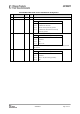
3:2 AGC_FREEZE[1:0] 0 (00) R/W Control when the AGC gain should be frozen.
Setting Function
0 (00) Normal operation. Always adjust gain when required.
1 (01)
The gain setting is frozen when a sync word has been
found.
2 (10)
Manually freeze the analogue gain setting and
continue to adjust the digital gain.
3 (11)
Manually freezes both the analogue and the digital
gain setting. Used for manually overriding the gain.
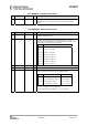
1:0 FILTER_LENGTH[1:0] 1 (01) R/W Sets the averaging length for the amplitude from the channel filter.
Sets the OOK/ASK decision boundary for OOK/ASK reception.
Setting Channel filter
samples
OOK decision
0 (00) 8 4 dB
1 (01) 16 8 dB
2 (10) 32 12 dB
3 (11) 64 16 dB
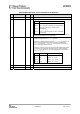
0x1E: WOREVT1 – High Byte Event0 Timeout
Bit Field Name Reset R/W Description
7:0 EVENT0[15:8] 135 (0x87) R/W
High byte of EVENT0 timeout register
RESWOR
XOSC
Event
EVENT
f
t
_5
0
20
750
⋅
⋅⋅=