
Data Sheet


CC1101
SWRS061B Page 77 of 93
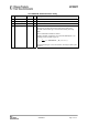
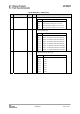
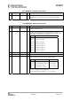
0x1B: AGCCTRL2 – AGC Control
Bit Field Name Reset R/W Description
7:6 MAX_DVGA_GAIN[1:0] 0 (00) R/W Reduces the maximum allowable DVGA gain.
Setting Allowable DVGA settings
0 (00) All gain settings can be used
1 (01) The highest gain setting can not be used
2 (10) The 2 highest gain settings can not be used
3 (11) The 3 highest gain settings can not be used
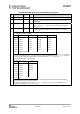
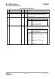
5:3 MAX_LNA_GAIN[2:0] 0 (000) R/W Sets the maximum allowable LNA + LNA 2 gain relative to the
maximum possible gain.
Setting Maximum allowable LNA + LNA 2 gain
0 (000) Maximum possible LNA + LNA 2 gain
1 (001) Approx. 2.6 dB below maximum possible gain
2 (010) Approx. 6.1 dB below maximum possible gain
3 (011) Approx. 7.4 dB below maximum possible gain
4 (100) Approx. 9.2 dB below maximum possible gain
5 (101) Approx. 11.5 dB below maximum possible gain
6 (110) Approx. 14.6 dB below maximum possible gain
7 (111) Approx. 17.1 dB below maximum possible gain
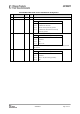
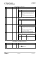
2:0 MAGN_TARGET[2:0] 3 (011) R/W These bits set the target value for the averaged amplitude from the
digital channel filter (1 LSB = 0 dB).
Setting Target amplitude from channel filter
0 (000) 24 dB
1 (001) 27 dB
2 (010) 30 dB
3 (011) 33 dB
4 (100) 36 dB
5 (101) 38 dB
6 (110) 40 dB
7 (111) 42 dB