
Data Sheet


CC1101
SWRS061B Page 74 of 93
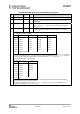
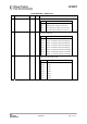
0x18: MCSM0– Main Radio Control State Machine Configuration
Bit Field Name Reset R/W Description
7:6 Reserved R0
5:4 FS_AUTOCAL[1:0] 0 (00) R/W Automatically calibrate when going to RX or TX, or back to IDLE
Setting When to perform automatic calibration
0 (00) Never (manually calibrate using SCAL strobe)
1 (01) When going from IDLE to RX or TX (or FSTXON)
2 (10)
When going from RX or TX back to IDLE
automatically
3 (11)
Every 4
th
time when going from RX or TX to IDLE
automatically
In some automatic wake-on-radio (WOR) applications, using setting 3 (11)
can significantly reduce current consumption.
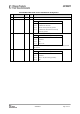
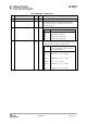
3:2 PO_TIMEOUT 1 (01) R/W Programs the number of times the six-bit ripple counter must expire after
XOSC has stabilized before CHP_RDYn goes low.
If XOSC is on (stable) during power-down, PO_TIMEOUT should be set so
that the regulated digital supply voltage has time to stabilize before
CHP_RDYn goes low (PO_TIMEOUT=2 recommended). Typical start-up
time for the voltage regulator is 50 us.
If XOSC is off during power-down and the regulated digital supply voltage
has sufficient time to stabilize while waiting for the crystal to be stable,
PO_TIMEOUT can be set to 0. For robust operation it is recommended to
use PO_TIMEOUT=2.
Setting Expire count Timeout after XOSC start
0 (00) 1 Approx. 2.3 – 2.4 µs
1 (01) 16 Approx. 37 – 39 µs
2 (10) 64 Approx. 149 – 155 µs
3 (11) 256 Approx. 597 – 620 µs
Exact timeout depends on crystal frequency.
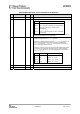
1 PIN_CTRL_EN 0 R/W Enables the pin radio control option
0 XOSC_FORCE_ON 0 R/W Force the XOSC to stay on in the SLEEP state.